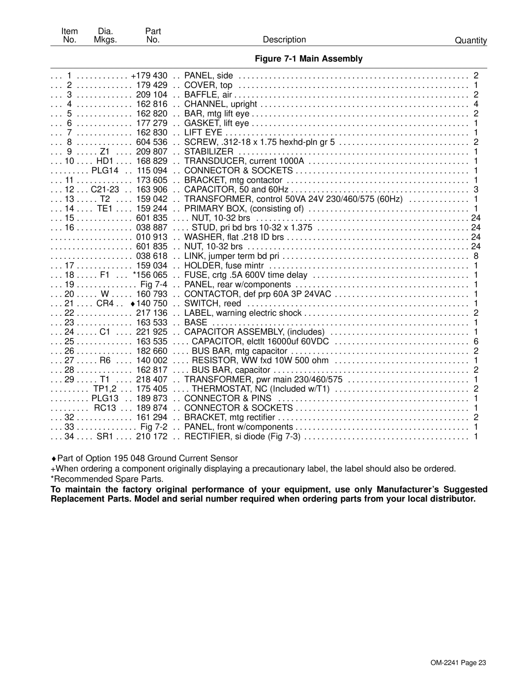
OM-2241 specifications
The Miller Electric OM-2241 is a versatile and innovative welding machine designed for both professional and industrial use. This power source is known for its durability, performance, and user-friendly features, making it a preferred choice for welders across various sectors.One of the main features of the OM-2241 is its advanced multi-process capabilities. This welding machine can seamlessly switch between MIG, TIG, stick, and flux-cored welding, allowing users to tackle a wide array of projects with ease. This flexibility makes it suitable for various applications, from maintenance and repair to fabrication and construction.
The OM-2241 is equipped with Miller's Auto-Set technology, which simplifies the setup process. This feature automatically adjusts the machine's settings based on the material thickness and type, enabling users to achieve optimal weld quality without the need for extensive calibration. This is particularly beneficial for both novice and experienced welders, as it reduces the learning curve and increases efficiency.
Another notable characteristic of the OM-2241 is its lightweight and portable design. Weighing significantly less than traditional welding machines, it allows for easy transportation, making it an excellent option for on-site work. The machine also boasts an ergonomic handle and intuitive control panel, enhancing user comfort and accessibility during operation.
In terms of performance, the OM-2241 provides a stable arc and reduced spatter, resulting in clean and professional-looking welds. Its built-in digital meter provides real-time feedback on voltage and amperage, allowing welders to monitor their performance closely and make adjustments as needed.
The Miller Electric OM-2241 is also engineered with durability in mind. Constructed with high-quality materials and protective features, it can withstand challenging working environments and ensure long-lasting operation. This resilience is complemented by Miller’s reputation for reliability and customer satisfaction, providing peace of mind to users.
In conclusion, the Miller Electric OM-2241 stands out in the welding equipment market due to its multifaceted capabilities, user-friendly technologies, and robust performance characteristics. Whether in a workshop or at a job site, this welding machine delivers the versatility and reliability required for various welding applications, making it an essential tool for any welder's arsenal.
