is done in time and the push button is working correctly, the display shows:

B U T T O N I S

W O R K I N G P R O P E R L Y

If the Purge push button tests okay, go to Step 5.

4.If the Purge push button is not pressed in time, or if the push button is not working correctly, the display shows:

6.Use the VOM to check for a dc voltage within the speci- fied range across pins C and D of the Remote 14 receptacle. If an acceptable voltage is present, go to Step 8.

7.If the correct dc input reference voltage is not found, contact the nearest Factory Authorized Service Station/Service Distributor.

8.When the analog output circuitry tests okay, press Pa- rameter Select to exit the test. Use the Right/Increase or Left/Decrease push button to access another test, or stop the diagnostics program.

B U T T O N I S N O T

W O R K I N G P R O P E R L Y

If the Purge push button is not working correctly, re- place the push button.

5.When the Purge push button tests okay, press Param- eter Select to exit the Purge push button test. Use the Right/Increase or Left/Decrease push button to access another test, or stop the diagnostics program (see Sec- tion 2-4).

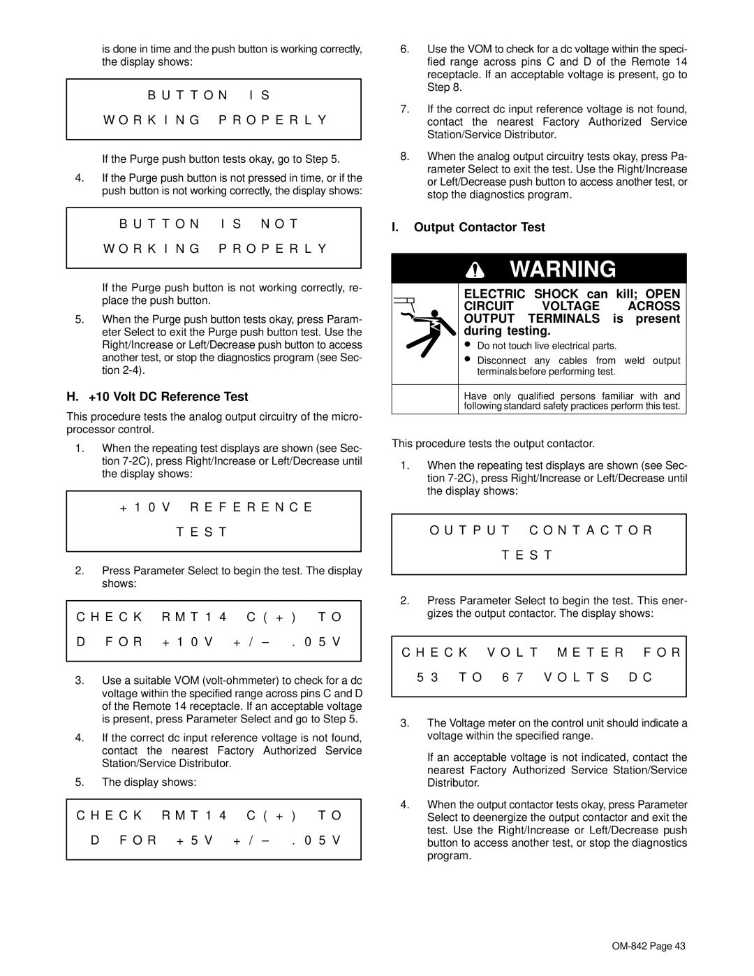
H.+10 Volt DC Reference Test

This procedure tests the analog output circuitry of the micro- processor control.

1.When the repeating test displays are shown (see Sec- tion 7-2C), press Right/Increase or Left/Decrease until the display shows:

+1 0 V R E F E R E N C E T E S T

2.Press Parameter Select to begin the test. The display shows:

C H E C K

R M T 1 4 C ( + )

T O

D F O R

+ 1 0 V + / – .

0 5 V


3.Use a suitable VOM (volt-ohmmeter) to check for a dc voltage within the specified range across pins C and D of the Remote 14 receptacle. If an acceptable voltage is present, press Parameter Select and go to Step 5.

4.If the correct dc input reference voltage is not found, contact the nearest Factory Authorized Service Station/Service Distributor.

5.The display shows:

C H E C K R M T 1 4 C ( + )

T O

D F O R + 5 V + / – .

0 5 V


I.Output Contactor Test

WARNING

ELECTRIC SHOCK can kill; OPEN

CIRCUIT VOLTAGE ACROSS OUTPUT TERMINALS is present during testing.

Do not touch live electrical parts.

Disconnect any cables from weld output terminals before performing test.

Have only qualified persons familiar with and following standard safety practices perform this test.

This procedure tests the output contactor.

1.When the repeating test displays are shown (see Sec- tion 7-2C), press Right/Increase or Left/Decrease until the display shows:

O U T P U T C O N T A C T O R

T E S T

2.Press Parameter Select to begin the test. This ener- gizes the output contactor. The display shows:

C H E C K V O L T M E T E R F O R

5 3 T O 6 7 V O L T S D C

3.The Voltage meter on the control unit should indicate a voltage within the specified range.

If an acceptable voltage is not indicated, contact the nearest Factory Authorized Service Station/Service Distributor.

4.When the output contactor tests okay, press Parameter Select to deenergize the output contactor and exit the test. Use the Right/Increase or Left/Decrease push button to access another test, or stop the diagnostics program.

OM-842 Page 43

Page 47
Image 47
Miller Electric OM-842 manual +10 Volt DC Reference Test

OM-842 specifications

The Miller Electric OM-842 is a versatile and powerful multi-process welding machine designed for professional welders who demand efficiency and reliability on the job. This industrial-grade welder is capable of handling various welding processes, including MIG, TIG, stick, and flux-cored welding, making it an ideal choice for a wide range of applications.

One of the standout features of the OM-842 is its robust output capability. With a maximum output of 400 amps, it can tackle thick materials with ease while maintaining exceptional arc stability. This output range allows for adaptability in different welding scenarios, whether working on heavy fabrication projects or lighter home repairs.

The OM-842 is also equipped with advanced inverter technology. This technology enhances the machine's efficiency and reduces energy consumption. Inverter machines are known for their lightweight design compared to traditional transformer welders, which makes the OM-842 more portable and easier to transport between job sites.

User-friendliness is paramount in the design of the OM-842. Its intuitive control panel features a digital display that provides real-time information on parameters such as voltage and amperage. This allows users to make quick and precise adjustments on the fly, enhancing productivity and ensuring optimal welding results.

Additionally, the OM-842 offers sophisticated weld control features, such as Auto-Set, which simplifies the setup process for beginners and experienced users alike. This technology automatically selects optimal parameters based on the material type and thickness, minimizing trial and error during welding.

The machine also includes a durable and rugged design, suitable for tough working conditions. The protective case and high-quality components ensure longevity and reliability even in adverse environments.

Safety is another critical aspect of the OM-842, with features such as over-temperature protection and a built-in fan to prevent overheating during extended use.

With its powerful performance, advanced technology, and robust design, the Miller Electric OM-842 stands out as an exceptional choice for welders seeking reliability and versatility in their welding operations, ultimately creating high-quality welds across various applications. Whether in a shop or on a construction site, the OM-842 is engineered to deliver outstanding results every time.