OM-842 specifications
The Miller Electric OM-842 is a versatile and powerful multi-process welding machine designed for professional welders who demand efficiency and reliability on the job. This industrial-grade welder is capable of handling various welding processes, including MIG, TIG, stick, and flux-cored welding, making it an ideal choice for a wide range of applications.One of the standout features of the OM-842 is its robust output capability. With a maximum output of 400 amps, it can tackle thick materials with ease while maintaining exceptional arc stability. This output range allows for adaptability in different welding scenarios, whether working on heavy fabrication projects or lighter home repairs.
The OM-842 is also equipped with advanced inverter technology. This technology enhances the machine's efficiency and reduces energy consumption. Inverter machines are known for their lightweight design compared to traditional transformer welders, which makes the OM-842 more portable and easier to transport between job sites.
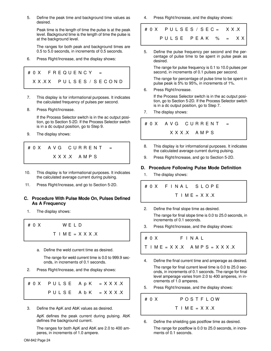
User-friendliness is paramount in the design of the OM-842. Its intuitive control panel features a digital display that provides real-time information on parameters such as voltage and amperage. This allows users to make quick and precise adjustments on the fly, enhancing productivity and ensuring optimal welding results.
Additionally, the OM-842 offers sophisticated weld control features, such as Auto-Set, which simplifies the setup process for beginners and experienced users alike. This technology automatically selects optimal parameters based on the material type and thickness, minimizing trial and error during welding.
The machine also includes a durable and rugged design, suitable for tough working conditions. The protective case and high-quality components ensure longevity and reliability even in adverse environments.
Safety is another critical aspect of the OM-842, with features such as over-temperature protection and a built-in fan to prevent overheating during extended use.
With its powerful performance, advanced technology, and robust design, the Miller Electric OM-842 stands out as an exceptional choice for welders seeking reliability and versatility in their welding operations, ultimately creating high-quality welds across various applications. Whether in a shop or on a construction site, the OM-842 is engineered to deliver outstanding results every time.

