SECTION 5 – PROGRAMMING

5-1. General

A. Displays

The displays presented by the microprocessor control either provide information to the user, or allow the user to enter infor- mation needed for program execution. The displays vary from mode to mode. Within each mode, the displays are always shown in the same sequence.

Pressing the Right/Increase push button allows the user to move forward through the sequence of displays, beginning to end. Pressing the Left/Decrease push button allows the user to move backward through the displays. Either push button can be used to access displays.

B. Selecting And Defining A Parameter

The user defines a parameter by entering a value for it. This is normally a three-step process (exceptions are noted in the text), that is carried out as follows:

1.Press Parameter Select (see Section 3-8) to select the parameter (the parameter flashes).

2.Press Right/Increase (see Section 3-9) or Left/De- crease (see Section 3-10) to enter the desired value.

3.Press Parameter Select again to deselect the parame- ter (the parameter stops flashing). If the display contains more than one parameter, the next parameter will be selected.

Parameters are always selected in sequence. If the existing value for the first parameter is acceptable, but another param- eter needs to be changed, use the Parameter Select push button to select and deselect the first parameter without changing its value. The next display in a mode cannot be ac- cessed if a parameter remains selected (flashing) in the existing display.

C. Defining Program Number

In some displays, the first parameter is the program number. This number provides a means of identifying programs en- tered into the selected mode. Since parameters are selected in sequence, even when the program number is not being changed it must be selected and deselected before the next parameter can be changed.

The program number is normally defined in the first display used to enter information. The defined number carries over to the following displays and does not need to be redefined as long as the original defined number applies.

To avoid unnecessary repetition, this manual does not indicate that the program number can be redefined in each display con- taining it. It is assumed that when a program is entered, each display in sequence applies to the same program.

D. Display Representation

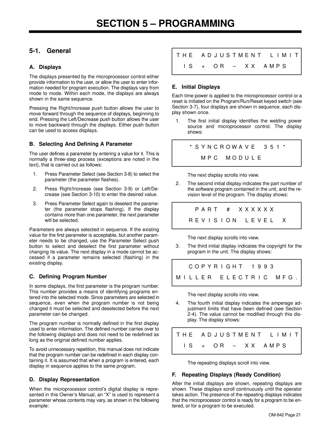
When the microprocessor control’s digital display is repre- sented in this Owner’s Manual, an “X” is used to represent a parameter whose contents may vary, as shown in the following example:

T H E

A D J U S T M E N T L I M I T

I S

+ O R – X X A M P S


E. Initial Displays

Each time power is applied to the microprocessor control or a reset is initiated on the Program/Run/Reset keyed switch (see Section 3-7), four displays are shown in sequence, each dis- play shown once.

1.The first initial display identifies the welding power source and microprocessor control. The display shows:

* S Y N C R O W A V E 3 5 1 *

M P C M O D U L E

The next display scrolls into view.

2.The second initial display indicates the part number of the software program contained in the unit, and the re- vision level of the program. The display shows:

P A R T

# X X X X X X

R E V I S

I O N L E V E L X


The next display scrolls into view.

3.The third initial display indicates the copyright for the program in the unit. The display shows:

C O P Y R I G H T 1 9 9 3

M I L L E R E L E C T R I C M F G .

The next display scrolls into view.

4.The fourth initial display indicates the amperage ad- justment limits that have been defined (see Section 2-4). The value cannot be modified through this dis- play. The display shows:

T H E

A D J U S T M E N T L I M I T

I S

+ O R – X X A M P S


The repeating displays scroll into view.

F.Repeating Displays (Ready Condition)

After the initial displays are shown, repeating displays are shown. These displays scroll continuously until the operator takes action. The presence of the repeating displays indicates that the microprocessor control is ready for a program to be en- tered, or for a program to be executed.

OM-842 Page 21

Page 25
Image 25
Miller Electric OM-842 manual Programming

OM-842 specifications

The Miller Electric OM-842 is a versatile and powerful multi-process welding machine designed for professional welders who demand efficiency and reliability on the job. This industrial-grade welder is capable of handling various welding processes, including MIG, TIG, stick, and flux-cored welding, making it an ideal choice for a wide range of applications.

One of the standout features of the OM-842 is its robust output capability. With a maximum output of 400 amps, it can tackle thick materials with ease while maintaining exceptional arc stability. This output range allows for adaptability in different welding scenarios, whether working on heavy fabrication projects or lighter home repairs.

The OM-842 is also equipped with advanced inverter technology. This technology enhances the machine's efficiency and reduces energy consumption. Inverter machines are known for their lightweight design compared to traditional transformer welders, which makes the OM-842 more portable and easier to transport between job sites.

User-friendliness is paramount in the design of the OM-842. Its intuitive control panel features a digital display that provides real-time information on parameters such as voltage and amperage. This allows users to make quick and precise adjustments on the fly, enhancing productivity and ensuring optimal welding results.

Additionally, the OM-842 offers sophisticated weld control features, such as Auto-Set, which simplifies the setup process for beginners and experienced users alike. This technology automatically selects optimal parameters based on the material type and thickness, minimizing trial and error during welding.

The machine also includes a durable and rugged design, suitable for tough working conditions. The protective case and high-quality components ensure longevity and reliability even in adverse environments.

Safety is another critical aspect of the OM-842, with features such as over-temperature protection and a built-in fan to prevent overheating during extended use.

With its powerful performance, advanced technology, and robust design, the Miller Electric OM-842 stands out as an exceptional choice for welders seeking reliability and versatility in their welding operations, ultimately creating high-quality welds across various applications. Whether in a shop or on a construction site, the OM-842 is engineered to deliver outstanding results every time.