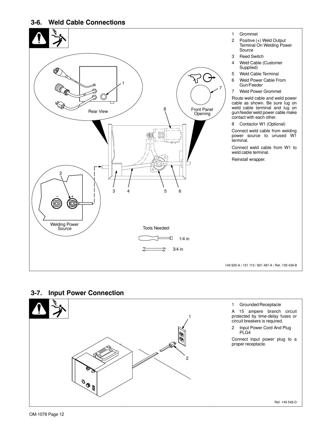
3-6. Weld Cable Connections
|
|
|
| 1 | Grommet |
|
|
|
| 2 | Positive (+) Weld Output |
|
|
|
|
| Terminal On Welding Power |
|
|
|
|
| Source |
|
|
|
| 3 | Reed Switch |
|
|
|
| 4 | Weld Cable (Customer |
|
|
|
|
| Supplied) |
|
|
|
| 5 | Weld Cable Terminal |
| 1 |
|
| 6 | Weld Power Cable From |
|
| 7 |
| Gun/Feeder | |
|
|
|
| ||
|
|
| 7 | Weld Power Grommet | |
|
|
|
| ||
|
|
|
| Route weld cable and weld power | |
|
|
|
| cable as shown. Be sure lug on | |
Rear View | 8 | Front Panel |
| weld cable terminal and lug on | |
| Opening |
| gun/feeder weld power cable make | ||
|
|
|
| contact with each other. | |
|
|
|
| 8 | Contactor W1 (Optional) |
|
|
|
| Connect weld cable from welding | |
|
|
|
| power source to unused W1 | |
|
|
|
| terminal. | |
|
|
|
| Connect weld cable from W1 to | |
|
|
|
| weld cable terminal. | |
|
|
|
| Reinstall wrapper. | |
2
3 | 4 | 5 | 6 |
−+
Welding Power | Tools Needed: |
Source |
1/4 in
3/4 in
149
3-7. Input Power Connection
|
| 1 | Grounded Receptacle |
|
| A | 15 ampere branch circuit |
| 1 | protected by | |
|
| circuit breakers is required. | |
|
| 2 | Input Power Cord And Plug |
|
|
| PLG4 |
Connect input power plug to a proper receptacle.
2
Ref. 149