5![]()
![]()
1
| I J | K | A |
Input Power Cord |
|
| B |
|
| L C | |
ConnectionTo | H | N | |
G | M | D | |
| |||
3 | F | E |
|
|
|
| |
2 | 5 |
|
|
|
|
| |
4 |
|
|
|
1 |
|
|
|
1 |
|
|
|
| 5 |
|
|
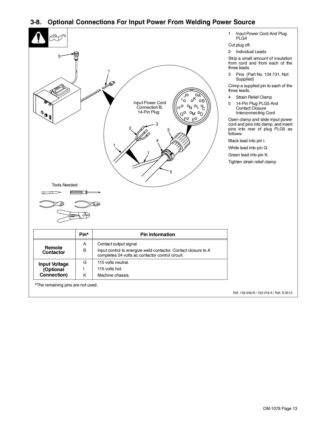
1Input Power Cord And Plug PLG4
Cut plug off.
2 Individual Leads
Strip a small amount of insulation from cord and from each of the three leads.
3Pins (Part No. 134 731, Not Supplied)
Crimp a supplied pin to each of the three leads.
4Strain Relief Clamp
5
Open clamp and slide input power cord and pins into clamp, and insert pins into rear of plug PLG5 as follows:
Black lead into pin I. White lead into pin G. Green lead into pin K. Tighten strain relief clamp.
Tools Needed:
| Pin* | Pin Information | |
|
|
| |
|
|
| |
Remote | A | Contact output signal. | |
B | Input control to energize weld contactor. Contact closure to A | ||
Contactor | |||
| completes 24 volts ac contactor control circuit. | ||
|
| ||
|
|
| |
Input Voltage | G | 115 volts neutral. | |
I | 115 volts hot. | ||
(Optional | |||
Connection) | K | Machine chassis. | |
|
|
|
*The remaining pins are not used.
Ref. 149