4-4. Common Work Connections
WARNING |
ELECTRIC SHOCK can kill. | ARCING can burn skin or damage | ||||
• | Do not touch live electrical parts. | electrical equipment. |
|
| |
• Turn Off welding power sources by placing Power | • Do not change position | of the | welding cable | ||
| circuit breakers in the Off position before making any | connectors while welding. |
|
| |
| • Be sure the connectors are secure in receptacles | ||||
• | weld output connections. | ||||
Do not connect welding output of different polarities | before welding. |
|
|
| |
• | to the same structure. | INADEQUATE | WORK | CABLE | |
See ANSI Z49.1 and OSHA Title 29, Chapter XVII, | CONNECTIONS | can | cause serious | ||
| Part 1910, Subpart Q (addresses at beginning of | damage to input power service and | |||
• | manual). | create a hazardous condition. | |||
Do not handle or come in contact with two live | • Connect an electrical cable of | adequate size | |||
| electrodes at the same time. | ||||
| between the isolated terminal and the workpiece | ||||
|
| ||||
|
| whenever any welding power sources are | |||
|
| connected to the isolated terminal. |
| ||
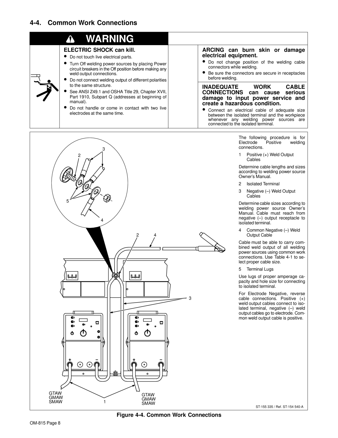
3
2
5
4
2 4
3
GTAW |
| GTAW | |
GMAW |
| ||
| GMAW | ||
SMAW | 1 | ||
SMAW | |||
|
|