4-6. Connecting Input Power To Rack
WARNING |
ELECTRIC SHOCK can kill. |
| |
• | Do not touch live electrical parts. |
|
• | Turn Off welding power sources before inspecting or installing rack. |
|
• | Have only qualified persons install rack. |
|
• | Installation must meet National Electrical Code and all other codes. | swarn3.1* 2/93 |
1 2
87
4
6 | 5 | 9 | 5 |
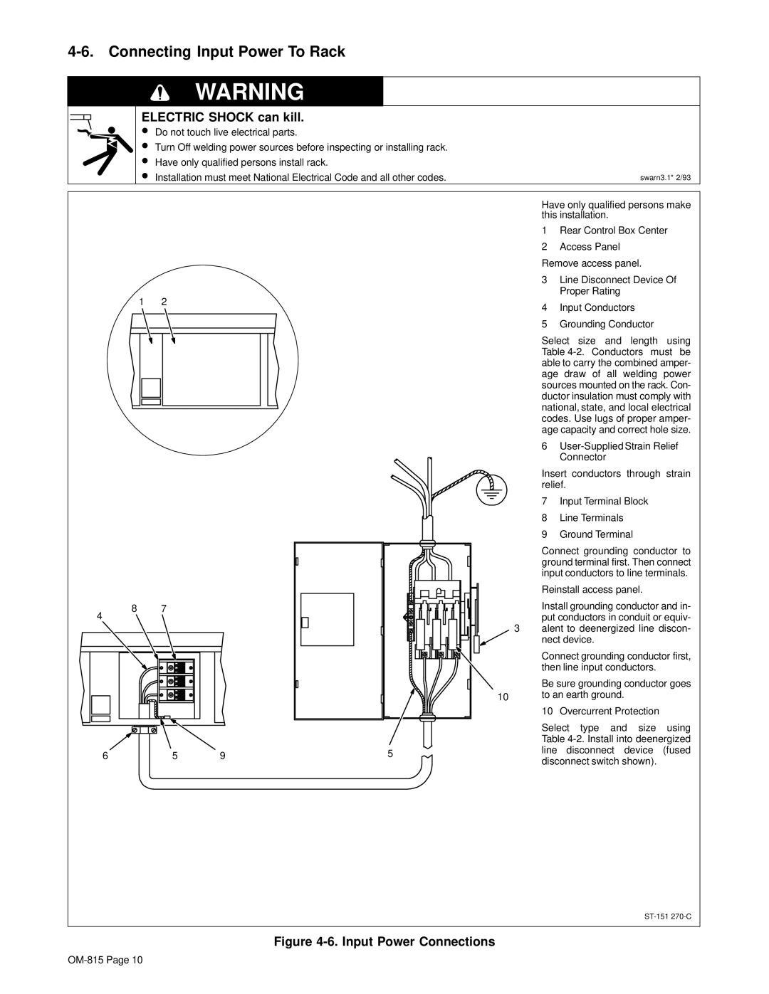
Have only qualified persons make this installation.
1Rear Control Box Center
2Access Panel
Remove access panel.
3Line Disconnect Device Of Proper Rating
4Input Conductors
5Grounding Conductor
Select size and length using Table
6
Insert conductors through strain relief.
7Input Terminal Block
8Line Terminals
9Ground Terminal
Connect grounding conductor to ground terminal first. Then connect input conductors to line terminals.
Reinstall access panel.
Install grounding conductor and in- put conductors in conduit or equiv-
3alent to deenergized line discon- nect device.
Connect grounding conductor first, then line input conductors.
Be sure grounding conductor goes
10to an earth ground.
10 Overcurrent Protection
Select type and size using Table