that can make a connection from one terminal to another. Shorting the battery terminals together may cause burns or a fire.
•Under abusive conditions, liquid may be ejected from the battery; avoid contact. If contact acci- dentally occurs, flush with water. If liquid contacts eyes, additionally seek medical help. Liquid ejected from the battery may cause irritation or burns.
SERVICE
•Have your power tool serviced by a qualified repair person using only identical replacement parts.
This will ensure that the safety of the power tool is maintained.
SYMBOLOGY
CE Conformity Mark
WARNING! To reduce the risk of personal injury, user must read and understand Operator’s Manual.
ASSEMBLY
Mounting on Workbench
The MILWAUKEE Band Saw Table must be mounted to a wooden or metal workbench with four bolts. Be sure to choose a location with sufficient room on each side to accommodate the cutting of long stock.
Mounting on Portable Legs
![]() WARNING To reduce the risk of per- sonal injury caused by tipping, use legs of equal lengths that will provide a comfortable
WARNING To reduce the risk of per- sonal injury caused by tipping, use legs of equal lengths that will provide a comfortable
For use with Band Saws requiring the ![]()
![]()
![]()
The MILWAUKEE Band Saw Table is shipped with the
NOTE: Retain all hardware for mounting the
Removing the
Mounting Bracket/Block | For use with: | |||||||
Most | ||||||||
(Installed) | ||||||||
|
|
|
|
|
|
|
| |
|
|
|
|
|
|
|
| |
|
|
|
|
|
|
|
| |
|
|
|
|
|
|
|
| |
|
|
|
|
|
|
|
|
|
Most | ||||||||
(Packaged separately in box) | ||||||||
|
|
|
|
|
|
|
| 6223 Deep Cut Band Saw |
|
|
|
|
|
|
|
| |
|
|
|
|
|
|
|
| 6225 Deep Cut Band Saw |
|
|
|
|
|
|
|
| |
|
|
|
|
|
|
|
| 6230 Deep Cut Band Saw |
|
|
|
|
|
|
|
| |
|
|
|
|
|
|
|
| 6232 Band Saw |
|
|
|
|
|
|
|
| 6232N Deep Cut Band Saw |
|
|
|
|
|
|
|
| 6236 Deep Cut Band Saw |
|
|
|
|
|
|
|
| 6236N Deep Cut Band Saw |
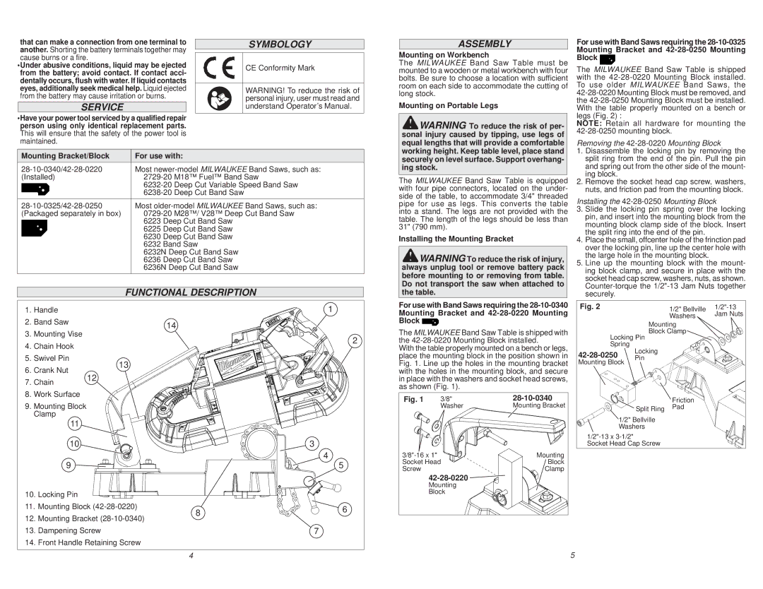
FUNCTIONAL DESCRIPTION
1. | Handle |
|
|
| 1 |
2. | Band Saw |
|
| 14 |
|
3. | Mounting Vise |
|
|
| |
|
|
| 2 | ||
4. | Chain Hook |
|
|
| |
|
|
|
| ||
5. | Swivel Pin |
| 13 |
|
|
6. | Crank Nut |
|
|
| |
12 |
|
|
| ||
7. | Chain |
|
|
| |
|
|
|
| ||
8. | Work Surface |
|
|
|
|
9. | Mounting Block |
|
|
|
|
| Clamp |
|
|
|
|
| 11 |
|
|
|
|
| 10 |
|
|
| 3 |
|
|
|
|
| 4 |
| 9 |
|
|
| 5 |
10. Locking Pin |
|
|
|
| |
11. Mounting Block | 8 | 6 | |||
12. Mounting Bracket |
| ||||
|
| ||||
13. Dampening Screw |
|
| 7 | ||
14. Front Handle Retaining Screw |
|
| |||
working height. Keep table level, place stand securely on level surface. Support overhang- ing stock.
The MILWAUKEE Band Saw Table is equipped with four pipe connectors, located on the under- side of the table, to accommodate 3/4" threaded pipe for use as legs. This converts the table into a stand. The legs are not provided with the table. The length of the legs should be less than 31" (790 mm).
Installing the Mounting Bracket
![]() WARNING To reduce the risk of injury, always unplug tool or remove battery pack before mounting to or removing from table. Do not transport the saw when attached to the table.
WARNING To reduce the risk of injury, always unplug tool or remove battery pack before mounting to or removing from table. Do not transport the saw when attached to the table.
For use with Band Saws requiring the ![]()
The MILWAUKEE Band Saw Table is shipped with the
With the table properly mounted on a bench or legs, place the mounting block in the position shown in Fig. 1. Line up the holes in the mounting bracket with the holes in the mounting block, and secure in place with the washers and socket head screws, as shown (Fig. 1).
Fig. 1 | 3/8" | |
| Washer | Mounting Bracket |
Mounting | ||
Socket Head | Block | |
Screw |
| Clamp |
|
| |
| Mounting |
|
| Block |
|
1.Disassemble the locking pin by removing the split ring from the end of the pin. Pull the pin and spring out from the other side of the mount- ing block.
2.Remove the socket head cap screw, washers, nuts, and friction pad from the mounting block.
Installing the 42-28-0250 Mounting Block
3.Slide the locking pin spring over the locking pin, and insert into the mounting block from the mounting block clamp side of the block. Insert the split ring into the end of the pin.
4.Place the small, offcenter hole of the frinction pad over the locking pin, line up the center hole with the large hole in the mounting block.
5.Line up the mounting block with the mount- ing block clamp, and secure in place with the socket head cap screw, washers, nuts, as shown.
Fig. 2 |
| 1/2" Bellville | |
|
| Washers | Jam Nuts |
| Mounting |
| |
Locking Pin Block Clamp |
| ||
Spring | Locking |
|
|
|
|
| |
Pin |
|
| |
Mounting Block |
|
|
|
|
| Friction |
|
| Split Ring | Pad |
|
1/2" Bellville |
|
| |
Washers |
|
| |
|
|
| |
Socket Head Cap Screw |
|
| |
4 |
5