Adjusting the Miter Angle
The miter mechanism on the MILWAUKEE Magnum® Slide Compound Miter Saw has detent settings for commonly cut angles (0°, 15°, 22.5° 30°, and 45°). These detents make for quick, accurate set up of common angles. In addition to the
The saw cuts miter angles from 51° on the left to 59° on the right. Angle markings appear on the scale that runs along the perimeter of the base.
1.To select a positive angle stop, loosen the clamp handle.
Pull the detente override lever and rotate the turntable to the desired angle.
Tighten the clamp handle.
2.To select other angles, use the override mechanism, which allows quick and accurate adjustments at any angle.
Pull up on the detent override lever and lock it by pushing in the detent override lock.
Rotate the turntable to the desired angle. Tighten the clamp handle securely clockwise.
Adjusting the Bevel Angle
The bevel mechanism has two positive
1.To adjust the bevel angle, place one hand on the front handle for better control. Using the other hand, loosen the bevel adjustment lever counterclockwise
2.Pull or push the saw handle to desired position, using the bevel angle scale as a guide.
3.Tighten the bevel adjustment lever clockwise securely.
Adjusting the Depth of Cut (Fig. 4)
A hex cap screw with a lock nut controls the depth of cut. This cut can be adjusted when cutting grooves, rabbets, or other operations
Fig. 4 | Socket |
| head cap |
| screw |
locknut
1.Unplug the tool.
2.Loosen the lock nut by turning counterclockwise.
3.To set the saw for maximum depth of cut, unscrew the hex cap screw so that it doesn't extend from the bottom of the saw arm.
To limit the depth of cut, screw the hex cap screw through the saw arm. The more the screw is driven through the shallower the cut is.
4.Securely tighten the lock nut.
5.Make a sample cut and adjust as necessary.
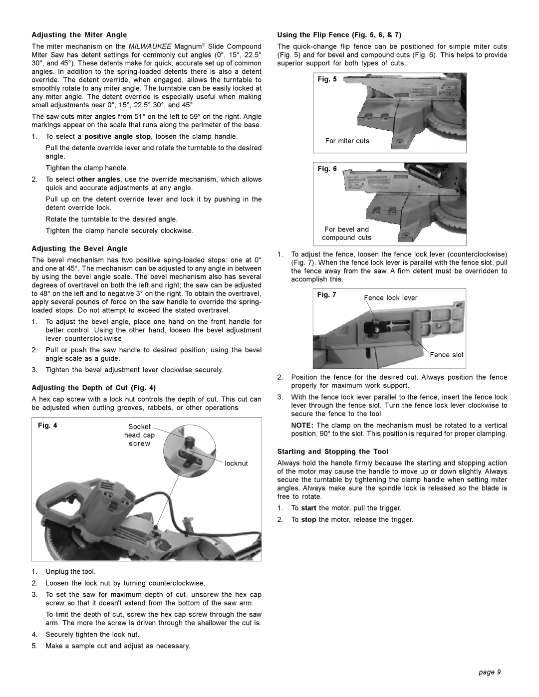
Using the Flip Fence (Fig. 5, 6, & 7)
The
Fig. 5
For miter cuts
Fig. 6
For bevel and compound cuts
1.To adjust the fence, loosen the fence lock lever (counterclockwise) (Fig. 7). When the fence lock lever is parallel with the fence slot, pull the fence away from the saw. A firm detent must be overridden to accomplish this.
Fig. 7 | Fence lock lever |
|
Fence slot
2.Position the fence for the desired cut. Always position the fence properly for maximum work support.
3.With the fence lock lever parallel to the fence, insert the fence lock lever through the fence slot. Turn the fence lock lever clockwise to secure the fence to the tool.
NOTE: The clamp on the mechanism must be rotated to a vertical position, 90° to the slot. This position is required for proper clamping.
Starting and Stopping the Tool
Always hold the handle firmly because the starting and stopping action of the motor may cause the handle to move up or down slightly. Always secure the turntable by tightening the clamp handle when setting miter angles. Always make sure the spindle lock is released so the blade is free to rotate.
1.To start the motor, pull the trigger.
2.To stop the motor, release the trigger.
page 9