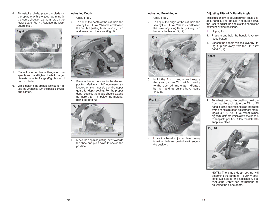
4.To install a blade, place the blade on the spindle with the teeth pointing in the same direction as the arrow on the lower guard (Fig. 4). Release the lower guard lever.
Fig. 4
5.Place the outer blade flange on the spindle and hand tighten the bolt. Larger diameter of outer flange (Fig. 3) should rest on blade.
6.While holding the spindle lock button in, use the wrench to turn the bolt clockwise and tighten.
Adjusting Depth
1.Unplug tool.
2.To adjust the depth of the cut, hold the saw by the
Fig. 5
3.Raise or lower the shoe to the desired position. Markings in 1/4" increments are located on the inner side of the upper guard for depth setting. For the proper depth setting, the blade should extend no more than 1/4" below the material being cut (Fig. 6).
Fig. 6
1/4"
4.Move the depth adjusting lever towards the shoe and push down to secure the
position.
Adjusting Bevel Angle
1.Unplug tool.
2.To adjust the angle of the cut, hold the saw by the
Fig. 7
3.Hold the front handle and rotate the saw by the
Fig. 8
4.Move the bevel adjusting lever away from the blade and push down to secure the position.
Adjusting Tilt-Lok™ Handle Angle
This circular saw is equipped with an adjust- able handle. The
1.Unplug tool.
2.Press in and hold the handle lever re- lease button.
3.Loosen the handle release lever by lift- ing it up and away from the
Fig. 9
4.To adjust the handle position, hold the front handle and rotate the
Fig. 10
NOTE: The blade depth setting will determine the range of
10 | 11 |