OPERATION:
• Connect the supplied 12 VDC power adapter to the meter and to the mains.
•Connect the pH and ORP electrode to the BNC socket of the meter.
• Always remove the electrode protec- tive caps before taking any measurement. If the electrodes have been left dry, soak the tip (bottom 2.5 cm) in rinse solution (M10000B) for a few minutes to reactivate them.
• Make sure that the meter has been calibrated before taking any measure- ments (see Calibration Procedure).
•Immerse the tip (2.5 cm) of the electrodes into the samples.
•Turn the instrument on by pressing the ON/OFF key.
•Allow the reading to stabilize and the meter will start con- tinuous monitoring.
•A blinking alarm LED will indicate when the measured pH value is higher than the setpoint and ORP value is lower than setpoint.
•When the alarm LED is blinking, there is power in the output power socket.
NOTE: The output power contact has no protection fuse inside the meter. It is recommended to protected it outside, against failure.
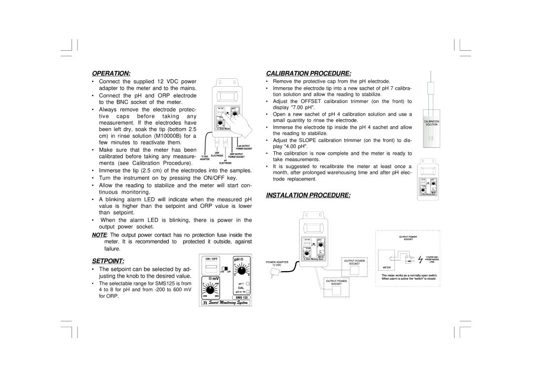
SETPOINT:
• The setpoint can be selected by ad- justing the knob to the desired value.
• The selectable range for SMS125 is from 4 to 8 for pH and from
CALIBRATION PROCEDURE:
•Remove the protective cap from the pH electrode.
•Immerse the electrode tip into a new sachet of pH 7 calibra- tion solution and allow the reading to stabilize.
•Adjust the OFFSET calibration trimmer (on the front) to display "7.00 pH".
•Open a new sachet of pH 4 calibration solution and use a small quantity to rinse the electrode.
•Immerse the electrode tip inside the pH 4 sachet and allow the reading to stabilize.
•Adjust the SLOPE calibration trimmer (on the front) to dis- play "4.00 pH".
•The calibration is now complete and the meter is ready to take measurements.
•It is suggested to recalibrate the meter at least once a month, after prolonged warehousing time and after pH elec- trode replacement.