LT-46246, LT-52246
LT-40148, LT-46148, LT-52148
For Your Records
Refer Servicing to Qualified Service Personnel
Contents
Outdoor Antenna Grounding
Replacement Parts
Disposal of Your TV
Installation Notes Cleaning Recommendations
TV Guide Daily Access Requirements
If Your TV Gets Damaged
Special Features of Your TV
Package Contents
Convenience Inputs
TV Control Panel Convenience Inputs
TV Guide Daily Interactive Program Guide System
Swivelling Stand
LED Color TV Condition Additional Information
Front-Panel Indicators
Power Indicator
Status Indicator
TV Main Panel
Selecting Audio Output Type, 246 Series TVs
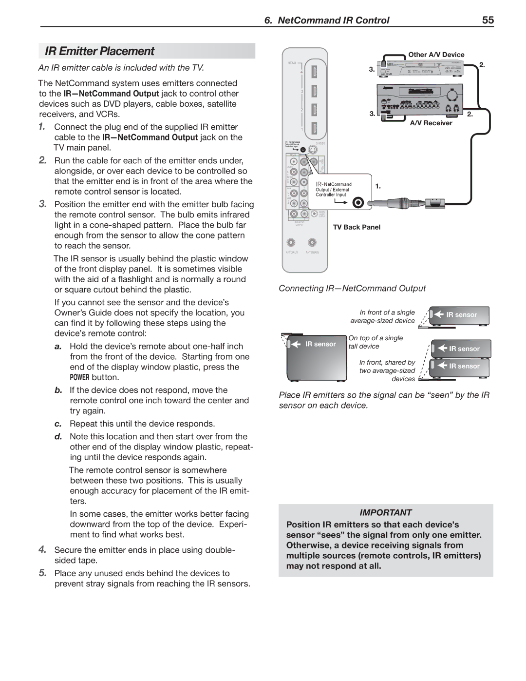
IR NetCommand Output/External Controller Input
Hdmi Inputs High-Definition Multimedia Interface
RS-232C
Stand Removal
Stand-Removal Procedure
TV Back Cover Protective Sheet
Getting Started
Guidelines for Setting Up and Using Your New Widescreen TV
Installing the Remote Control Batteries
When You First Power On the TV
Assistance
Additional TV Setup
TV Cleaning
TV Operation
Memorizing Channels
Initial TV Setup
Setting Up TV Inputs
When You First Connect a Device
Receiver
Auto Input Sensing for CEC-Enabled Devices
Setup Procedure
Auto Input/Auto Output Sensing Screens
With NetCommand for Hdmi CEC-Enabled Hdmi A/V Receiver
Controlling A/V Receiver Sound Volume
With a Standard TV Setup
With NetCommand IR Control
Source device connected directly to the TV
Computer Video Connection Audio Video Output
Connecting a Computer to the TV
Computer Display Formats
Using the TV with a Personal Computer
Computer Video Adjustments
Image Resolution
CableCARD Menu
Using a CableCARD
Installing a CableCARD
Series TVs
Cable Routing
Installing the Cable Tie
Before You Begin
Cable Management
Satellite dish
Cable service or
Hdmi and Audio Signals
Incoming from
Cables to Input
Connect audio
Audio
Antennas with Separate UHF and VHF Leads
Wall Outlet Cable no cable box
Antenna with a Single Lead
VCR to a Cable Box Audio & Video
VCR to an Antenna or Wall Outlet Cable
VCR
26 3. TV Connections
Older Cable Box
Receiver Sound System Using the TV’s Audio Output
Composite Video Connection
Camcorder
Audio-Only Device
Pb Pr Component Video Connection
Choosing a Viewing Source
Sleep Timer
TV Tips
Cancel
Remote Control
23. F1-F4 For devices under NetCommand control
ChannelView Channel Listings
TV-PG FAV1
Signal Strength
Status Display
Ant 1
ANT-1
Fav Favorite Channels
TV Display Format Definitions
TV Signals and Display Formats
Signal Definitions
DVD Image Definitions
Jpeg Images and the USB Photo Port
Viewing Camera Files
Jpeg Thumbnail Menu
Keys for Jpeg Picture Slide Show
Media Setup Menu
Camera Photos and Moving Video as Composite Video
Slide Show
Main Menu
Remote Control Keys for the TV Menu System
AV Menu Options
AV Menu
Audio Only On, Off
Film Mode Auto, Off
Video Mute On, Off
Global
Video Menu Options
Video Menu
Imager
Vert Adjustment
SharpEdge On, Off
DeepField
From the Audio menu
Audio Menu
Audio Menu Options
Captions Menu Options
Captions Menu
Captions on Analog Channels
Captions on Digital Channels
Setup Menu Options
Setup Menu
1 Enter
Edit
Setup menu, Edit channel options
Date
Clock
Time
Manual
Setup menu, Timer options
Timer
Use the External Controller Input Wired IR option see
Energy Fast Power On Mode Low Power
This page intentionally left blank
Selection menu
Only when Inputs NetCommand
Inputs Menu
Input Selection menu
Other Menu Alternate Rating System
Lock Menu
Pass Codes
Parent Menu
TV-G
Parent Menu Options U.S.-based rating system
TV-Y
TV-Y7
Time
Other Menu Options alternate rating system
Important Note on NetCommand
About NetCommand IR Control
An IR emitter cable is included with the TV
IR Emitter Placement
If the device has no Power OFF key, skip this step
Initial NetCommand Setup for Most Devices
Guide
Power
CH/PAGE
Special Operation Methods
Operating NetCommand-Controlled Devices
Controlling Most Device Types
Controlling an A/V Receiver
Outside the Guide
Inside the Guide
Before You Begin
Setting Up NetCommand Control of an A/V Receiver
Receiver Control Power and Volume
Setup to Control A/V Receiver Power and Volume
Analog Stereo Audio
Receiver Control Automatic Audio Switching
Audio Switching Setup
Audio Available from TV only
AV Receiver menu to set up audio switching
VCR
More About Using an Hdmi Connection with this Setup
AVR menu for audio and video switching with Hdmi output
Setup to Control Switching to the TV’s Audio Output
Open the Inputs Learn menu
NetCommand IR Control Device Connected to an A/V Receiver
Ated Assign Input column Assign Input1 through
Assign Input5
Width Depth Weight lbs
Appendix a Specifications
Bypassing the Parental Lock
Appendix B Bypassing the Parental Lock
This page intentionally left blank
Functions Available for Other A/V Devices
Appendix C Programming the Remote Control
Code Verification
Programming the Remote Control
DVD
CABLE/SAT VCR DVD Audio
Cable Boxes Make Code
Programming Codes
Make Code
Cable Boxes
Receivers Make Code
Laser Disc Players
Satellite Receivers Make Code
ABS
VCRs Make Code
DVD Players Make Code
DVD Players
Appendices75
High-definition ChannelIcon Number
Initial Guide Setup
Appendix D TV Guide Daily 246 Series TVs
Main Guide Screen Elements
Using the TV Guide Daily System
Setting Up TV Guide Daily
Navigating the Guide
Available Options
Modifying the Guide Setup
Looking at Ads
Customizing Guide Listings
TV Guide Daily Troubleshooting Tips Symptom Remarks
Procedure
Enabling or Disabling the TV’s NetCommand Hdmi Control
Appendix E NetCommand Hdmi Control of CEC Devices
Connecting Hdmi Devices to the TV
Appendices81
Resetting Hdmi Control or Removing an Hdmi Device Figure
Using NetCommand Hdmi Control
CEC-enabled A/V receiver functions that may be available
TV Reset Comparison Guide
Appendix F Troubleshooting
Reset Name When to Use How to Use Resulting Action
Tions
Service and Customer Support
Service
Read the ON-SCREEN
TV Channels Symptom Remarks
General TV Operation Symptom Remarks
Picture Symptom Remarks
TV Power On/Off Symptom Remarks
Symptom Remarks
NetCommand IR Control Symptom Remarks
Indicators Symptom Remarks
Appendices89
Trademark and License Information
Mitsubishi TV Software
This Limited Warranty does not Cover
To Obtain Warranty Service
Warranty93
Index
Index95
System Reset
MDEAservice@mdea.com