<RECORD SETTINGS> (continued)
9.(When setting the emergency recording camera • • • ) Turn the JOG dial and move the cursor to “EMR” and turn the SHUTTLE ring clockwise.
•The first item from the left side in the “ALARM RECORD CAMERA” setting display reverses in color.
10.Repeat steps 5, 6 for settings.
11.When the setting is complete, turn the SHUTTLE ring counterclockwise.
•The cursor moves to the camera number on the left.
•When continuing with other camera number settings, turn the JOG dial to move the cursor to the desired camera number and repeat steps 4 ~ 11 to perform the settings.
12.(When setting recording intervals and recording picture quality • • • )
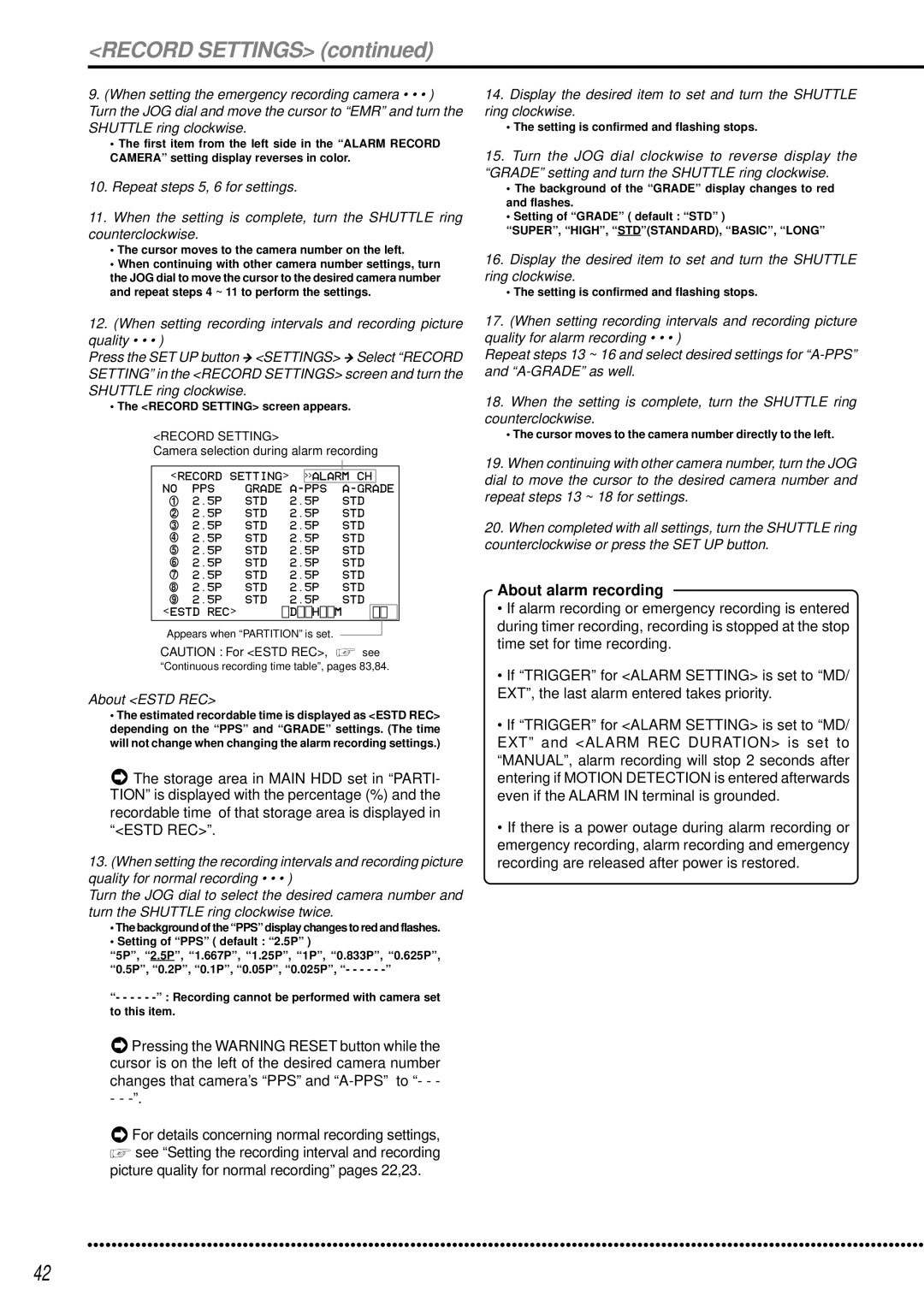
Press the SET UP button } <SETTINGS> } Select “RECORD SETTING” in the <RECORD SETTINGS> screen and turn the SHUTTLE ring clockwise.
•The <RECORD SETTING> screen appears.
<RECORD SETTING>
Camera selection during alarm recording
|
|
|
|
|
|
|
|
|
|
<RECORD SETTING> |
| >>ALARM CH |
| ||||||
NO | PPS | GRADE | A- | PPS |
| ||||
1 | 2.5P | STD | 2.5P |
| STD | ||||
2 | 2.5P | STD | 2.5P |
| STD | ||||
3 | 2.5P | STD | 2.5P |
| STD | ||||
4 | 2.5P | STD | 2.5P |
| STD | ||||
5 | 2.5P | STD | 2.5P |
| STD | ||||
6 | 2.5P | STD | 2.5P |
| STD | ||||
7 | 2.5P | STD | 2.5P |
| STD | ||||
8 | 2.5P | STD | 2.5P |
| STD | ||||
9 | 2.5P | STD | 2.5P |
| STD | ||||
<ESTD REC> |
| D H | M |
| |||||
Appears when “PARTITION” is set.
CAUTION : For <ESTD REC>, ![]() see
see
“Continuous recording time table”, pages 83,84.
About <ESTD REC>
•The estimated recordable time is displayed as <ESTD REC> depending on the “PPS” and “GRADE” settings. (The time will not change when changing the alarm recording settings.)
![]() The storage area in MAIN HDD set in “PARTI- TION” is displayed with the percentage (%) and the recordable time of that storage area is displayed in “<ESTD REC>”.
The storage area in MAIN HDD set in “PARTI- TION” is displayed with the percentage (%) and the recordable time of that storage area is displayed in “<ESTD REC>”.
13.(When setting the recording intervals and recording picture quality for normal recording • • • )
Turn the JOG dial to select the desired camera number and turn the SHUTTLE ring clockwise twice.
•The background of the “PPS” display changes to red and flashes.
•Setting of “PPS” ( default : “2.5P” )
“5P”, “2.5P”, “1.667P”, “1.25P”, “1P”, “0.833P”, “0.625P”, “0.5P”, “0.2P”, “0.1P”, “0.05P”, “0.025P”, “- - - - -
“- - - - -
![]() Pressing the WARNING RESET button while the cursor is on the left of the desired camera number changes that camera’s “PPS” and
Pressing the WARNING RESET button while the cursor is on the left of the desired camera number changes that camera’s “PPS” and
- -
![]() For details concerning normal recording settings,
For details concerning normal recording settings, ![]() see “Setting the recording interval and recording
see “Setting the recording interval and recording
picture quality for normal recording” pages 22,23.
14.Display the desired item to set and turn the SHUTTLE ring clockwise.
•The setting is confirmed and flashing stops.
15.Turn the JOG dial clockwise to reverse display the “GRADE” setting and turn the SHUTTLE ring clockwise.
•The background of the “GRADE” display changes to red and flashes.
•Setting of “GRADE” ( default : “STD” )
“SUPER”, “HIGH”, “STD”(STANDARD), “BASIC”, “LONG”
16.Display the desired item to set and turn the SHUTTLE ring clockwise.
•The setting is confirmed and flashing stops.
17.(When setting recording intervals and recording picture quality for alarm recording • • • )
Repeat steps 13 ~ 16 and select desired settings for
18.When the setting is complete, turn the SHUTTLE ring counterclockwise.
•The cursor moves to the camera number directly to the left.
19.When continuing with other camera number, turn the JOG dial to move the cursor to the desired camera number and repeat steps 13 ~ 18 for settings.
20.When completed with all settings, turn the SHUTTLE ring counterclockwise or press the SET UP button.
About alarm recording
•If alarm recording or emergency recording is entered during timer recording, recording is stopped at the stop time set for time recording.
•If “TRIGGER” for <ALARM SETTING> is set to “MD/ EXT”, the last alarm entered takes priority.
•If “TRIGGER” for <ALARM SETTING> is set to “MD/ EXT” and <ALARM REC DURATION> is set to “MANUAL”, alarm recording will stop 2 seconds after entering if MOTION DETECTION is entered afterwards even if the ALARM IN terminal is grounded.
•If there is a power outage during alarm recording or emergency recording, alarm recording and emergency recording are released after power is restored.
••••••••••••••••••••••••••••••••••••••••••••••••••••••••••••••••••••••••••••••••••••••••••••••••••••••••••••••••••••••••••••••• | ••••••••••••• |
42
