Manuals
/
Mitsubishi Electronics
/
Computer Equipment
/
Projector
Mitsubishi Electronics
HC910
user manual
Connectors, EN-37, English
Models:
HC910
1
37
38
38
Download
38 pages
58.32 Kb
31
32
33
34
35
36
37
38
Troubleshooting
Install
SIGNAL menu
Password
Indicators
Connecting to a DVD player
Dimension
Maintenance
Checking accessories
Basic setup
Page 37
Image 37
Page 36
Page 38
Page 37
Image 37
Page 36
Page 38
Contents
HC910
MODEL
HC910
User Manual
REFER SERVICING TO QUALIFIED SERVICE PERSONNEL
SHOCK, DO NOT REMOVE COVER OR BACK NO USER-SERVICEABLE PARTS INSIDE
When using the projector in Europe COMPLIANCE NOTICE
CAUTION TO REDUCE THE RISK OF ELECTRIC
Declaration of Conformity
Contents
Trademark, Registered trademark
EN-4
Important safeguards
Do not look into the air outlet grille when projector is operating
Do not look into the lens when it is operating. It may hurt your eyes
Place of installation
Unplug immediately if there is something wrong with your projector
Inserting the batteries into the remote control
Checking accessories
Preparing your projector
Power supply parts
Control area
Overview
Terminal panel
5 Remote control sensor Front 6 Air inlet grille 7 Air outlet grille
Using the picture quality adjusting buttons
Remote control
Preparating your projector Continue
Bottom side
Operational range of the remote control
Using the remote control
Reception angle
Front of projector
Setting up the screen
Setting up your projector
Basic setup
Adjusting the projection angle
Screen size and projection distance
When the aspect ratio of the screen is
EN-11
Viewing video images
A. Connecting the projector to video equipment
Basic home theater system connection
Preparation
Connecting to a DVD player
Connecting to a video player, etc
When a TV tuner or VCR is connected
EN-13
Connecting to video equipment having a DVI-D terminal
B. Plugging in the power cord
Viewing video images continued
EN-15
C. Projecting images
To stop projecting
When projected images are distorted to a trapezoid
IRIS button
With the INSTALLATION menu
How to change the settings
Setting the aspect ratio
With the remote control
With the FEATURE menu
B. Plugging the power cord
A. Connecting the projector to a computer
Viewing computer images
For analog connection
EN-19
C. Projecting images
Viewing computer images continued
When connecting to a notebook computer
AUTO POSITION button
Example of the setting procedure for external output
Menu operation
How to set the menus
Menu operation continued
Available settings in the menus
2. INSTALLATION menu
1. IMAGE menu
4. SIGNAL menu
3. FEATURE menu
EN-23
AUTO
To adjust the brightness CONTRAST and BRIGHTNESS
Adjusting projected images
To adjust the color COLOR and TINT
To sharpen or soften the projected image SHARPNESS
To adjust the tone of white To customize the color temperature
To adjust the tone of white COLOR TEMP
About color temperature
AV MEMORY
How to adjust the image supplied from the computer using the menu
Adjusting projected images continued
Simple method to adjust the image position
To adjust the horizontal position
Password function
Advanced features
To enable the password function
To cancel the password function
Dimension Drawings unit mm
Asking for installation
To view images projected on the translucent screen from behind
Installation
Using filter
Cleaning
Cleaning the filter
Interval of lamp replacement
Replacing the lamp
EN-30
Cleaning of the projector and the ventilation slots
Maintenance
Cleaning of the lens
To replace the lamp
Problem
Troubleshooting
Solution
EN-32
Images are not displayed correctly
No image appears on the screen. Continued
Kensington Lock
Troubleshooting continued
Others
Normal condition
Indicators
Abnormal condition
Specifications
Replacement part Option / Not included in the box
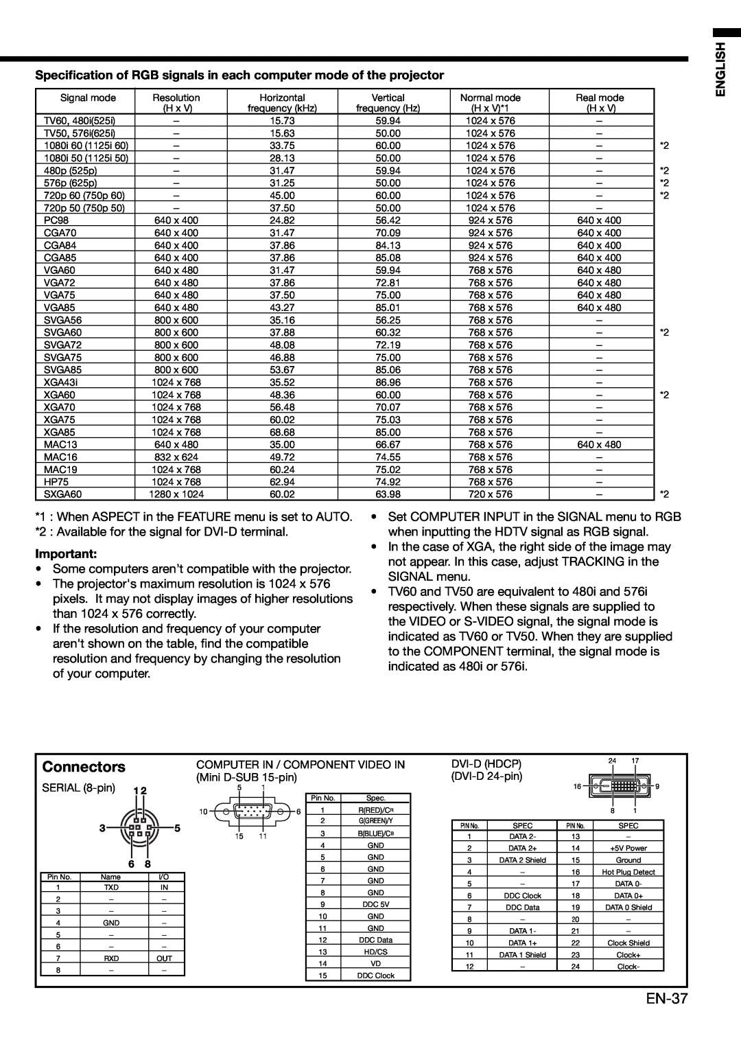
Specification of RGB signals in each computer mode of the projector
Connectors
EN-37
MITSUBISHI ELECTRIC CORPORATION
MITSUBISHI Projector Contact Information
871D420A70
Printed in Japan
Top
Page
Image
Contents