STK17T88
Register Map Detail (continued)
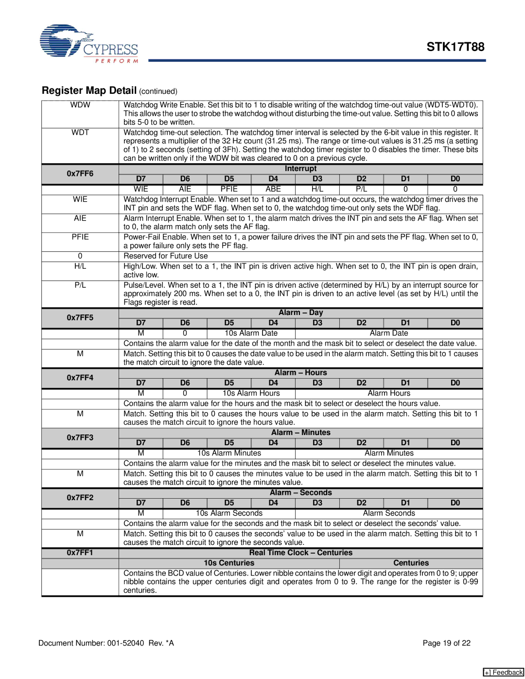
WDW | Watchdog Write Enable. Set this bit to 1 to disable writing of the watchdog | |||||||||||
| This allows the user to strobe the watchdog without disturbing the | |||||||||||
| bits |
|
|
|
|
|
|
|
|
| ||
WDT | Watchdog | |||||||||||
| represents a multiplier of the 32 Hz count (31.25 ms). The range or | |||||||||||
| of 1) to 2 seconds (setting of 3Fh). Setting the watchdog timer register to 0 disables the timer. These bits | |||||||||||
| can be written only if the WDW bit was cleared to 0 on a previous cycle. |
|
|
|
| |||||||
0x7FF6 |
|
|
|
|
| Interrupt |
|
|
|
|
| |
D7 | D6 |
| D5 | D4 |
| D3 | D2 |
| D1 |
| D0 | |
|
|
|
|
| ||||||||
| WIE | AIE |
| PFIE | ABE |
| H/L | P/L |
| 0 |
| 0 |
WIE | Watchdog | Interrupt Enable. When set to 1 and a watchdog | ||||||||||
| INT pin and sets the WDF flag. When set to 0, the watchdog |
| ||||||||||
AIE | Alarm Interrupt Enable. When set to 1, the alarm match drives the INT pin and sets the AF flag. When set | |||||||||||
| to 0, the alarm match only sets the AF flag. |
|
|
|
|
|
|
| ||||
PFIE | ||||||||||||
| a power failure only sets the PF flag. |
|
|
|
|
|
|
|
| |||
0 | Reserved for Future Use |
|
|
|
|
|
|
|
|
| ||
H/L | High/Low. When set to a 1, the INT pin is driven active high. When set to 0, the INT pin is open drain, | |||||||||||
| active low. |
|
|
|
|
|
|
|
|
|
|
|
P/L | Pulse/Level. When set to a 1, the INT pin is driven active (determined by H/L) by an interrupt source for | |||||||||||
| approximately 200 ms. When set to a 0, the INT pin is driven to an active level (as set by H/L) until the | |||||||||||
| Flags register is read. |
|
|
|
|
|
|
|
|
| ||
0x7FF5 |
|
|
|
| Alarm – Day |
|
|
|
|
| ||
D7 | D6 | D5 | D4 |
| D3 | D2 |
| D1 |
| D0 | ||
|
|
|
| |||||||||
| M | 0 |
| 10s Alarm Date |
|
|
| Alarm Date |
| |||
Contains the alarm value for the date of the month and the mask bit to select or deselect the date value.
MMatch. Setting this bit to 0 causes the date value to be used in the alarm match. Setting this bit to 1 causes the match circuit to ignore the date value.
0x7FF4 |
|
|
| Alarm – Hours |
|
|
| ||
D7 | D6 | D5 | D4 | D3 | D2 | D1 | D0 | ||
| |||||||||
| M | 0 | 10s Alarm Hours |
|
| Alarm Hours |
| ||
Contains the alarm value for the hours and the mask bit to select or deselect the hours value.
MMatch. Setting this bit to 0 causes the hours value to be used in the alarm match. Setting this bit to 1 causes the match circuit to ignore the hours value.
0x7FF3 |
|
|
| Alarm – Minutes |
|
|
| ||
D7 | D6 | D5 | D4 | D3 | D2 | D1 | D0 | ||
| |||||||||
| M |
| 10s Alarm Minutes |
|
| Alarm Minutes |
| ||
Contains the alarm value for the minutes and the mask bit to select or deselect the minutes value.
MMatch. Setting this bit to 0 causes the minutes value to be used in the alarm match. Setting this bit to 1 causes the match circuit to ignore the minutes value.
0x7FF2 |
|
|
| Alarm – Seconds |
|
|
| ||
D7 | D6 | D5 | D4 | D3 | D2 | D1 | D0 | ||
| |||||||||
| M |
| 10s Alarm Seconds |
|
| Alarm Seconds |
| ||
Contains the alarm value for the seconds and the mask bit to select or deselect the seconds’ value.
MMatch. Setting this bit to 0 causes the seconds’ value to be used in the alarm match. Setting this bit to 1 causes the match circuit to ignore the seconds value.
0x7FF1 | Real Time Clock – Centuries |
| |
| 10s Centuries |
| Centuries |
| Contains the BCD value of Centuries. Lower nibble contains the | lower digit and operates from 0 to 9; upper | |
| nibble contains the upper centuries digit and operates from 0 to 9. The range for the register is | ||
| centuries. |
| |
Document Number: | Page 19 of 22 |
[+] Feedback