STK17T88
Register Map Detail
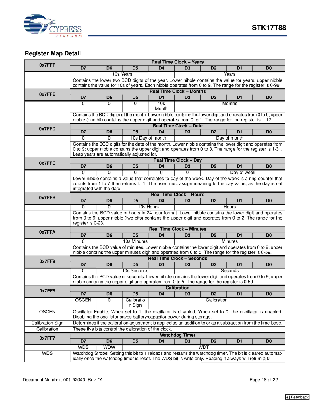
| 0x7FFF |
|
|
|
| Real Time Clock – Years |
|
|
|
| |||
| D7 |
| D6 | D5 | D4 | D3 |
| D2 |
| D1 |
| D0 | |
|
|
|
|
|
| ||||||||
|
|
|
| 10s | Years |
|
|
|
|
| Years |
|
|
|
| Contains the lower two BCD digits of the year. Lower nibble contains the value for years; upper nibble | |||||||||||
|
| contains the value for 10s of years. Each nibble operates from 0 to 9. The range for the register is | |||||||||||
| 0x7FFE |
|
|
|
| Real Time Clock – Months |
|
|
|
| |||
| D7 |
| D6 | D5 | D4 | D3 |
| D2 |
| D1 |
| D0 | |
|
|
|
|
|
| ||||||||
|
| 0 |
| 0 | 0 | 10s |
|
|
| Months |
| ||
|
|
|
|
|
| Month |
|
|
|
|
|
|
|
|
| Contains the BCD digits of the month. Lower nibble contains the lower digit and operates from 0 to 9; upper | |||||||||||
|
| nibble (one bit) contains the upper digit and operates from 0 to 1. The range for the register is | |||||||||||
| 0x7FFD |
|
|
|
| Real Time Clock – Date |
|
|
|
| |||
| D7 |
| D6 | D5 | D4 | D3 |
| D2 |
| D1 |
| D0 | |
|
|
|
|
|
| ||||||||
|
| 0 |
| 0 | 10s Day | of month |
|
| Day | of month |
| ||
|
| Contains the BCD digits for the date of the month. Lower nibble contains the lower digit and operates from | |||||||||||
|
| 0 to 9; upper nibble contains the upper digit and operates from 0 to 3. The range for the register is | |||||||||||
|
| Leap years are automatically adjusted for. |
|
|
|
|
|
|
| ||||
| 0x7FFC |
|
|
|
| Real Time Clock – Day |
|
|
|
| |||
| D7 |
| D6 | D5 | D4 | D3 |
| D2 |
| D1 |
| D0 | |
|
|
|
|
|
| ||||||||
|
| 0 |
| 0 | 0 | 0 | 0 |
|
|
| Day of week |
|
|
|
| Lower nibble | contains a | value that | correlates to day of the week. Day of the week is a ring counter that | ||||||||
|
| counts from 1 to 7 then returns to 1. The user must assign meaning to the day value, as the day is not | |||||||||||
|
| integrated with the date. |
|
|
|
|
|
|
|
|
| ||
| 0x7FFB |
|
|
|
| Real Time Clock – Hours |
|
|
|
| |||
| D7 |
| D6 | D5 | D4 | D3 |
| D2 |
| D1 |
| D0 | |
|
|
|
|
|
| ||||||||
|
| 0 |
| 0 | 10s | Hours |
|
|
|
| Hours |
|
|
|
| Contains the BCD value of hours in 24 hour format. Lower nibble contains the lower digit and operates | |||||||||||
|
| from 0 to 9; upper nibble (two bits) contains the upper digit and operates from 0 to 2. The range for the | |||||||||||
|
| register is |
|
|
|
|
|
|
|
|
| ||
| 0x7FFA |
|
|
|
| Real Time Clock – Minutes |
|
|
|
| |||
| D7 |
| D6 | D5 | D4 | D3 |
| D2 |
| D1 |
| D0 | |
|
|
|
|
|
| ||||||||
|
| 0 |
|
| 10s Minutes |
|
|
|
| Minutes |
| ||
|
| Contains the BCD value of minutes. Lower nibble contains the lower digit and operates from 0 to 9; upper | |||||||||||
|
| nibble contains the upper minutes digit and operates from 0 to 5. The range for the register is | |||||||||||
| 0x7FF9 |
|
|
|
| Real Time Clock – Seconds |
|
|
|
| |||
| D7 |
| D6 | D5 | D4 | D3 |
| D2 |
| D1 |
| D0 | |
|
|
|
|
|
| ||||||||
|
| 0 |
|
| 10s Seconds |
|
|
|
| Seconds |
| ||
|
| Contains the BCD value of seconds. Lower nibble contains the lower digit and operates from 0 to 9; upper | |||||||||||
|
| nibble contains the upper digit and operates from 0 to 5. The range for the register is |
| ||||||||||
| 0x7FF8 |
|
|
|
| Calibration |
|
|
|
|
|
| |
| D7 |
| D6 | D5 | D4 | D3 |
| D2 |
| D1 |
| D0 | |
|
|
|
|
|
| ||||||||
|
| OSCEN |
| 0 | Calibratio |
|
|
| Calibration |
|
|
| |
|
|
|
|
| n Sign |
|
|
|
|
|
|
|
|
|
|
|
|
|
|
|
|
|
| ||||
| OSCEN | Oscillator | Enable. When | set to 1, the oscillator is disabled. When set to 0, the oscillator is enabled. | |||||||||
|
| Disabling the oscillator saves battery/capacitor power during storage. |
|
|
|
| |||||||
| Calibration Sign | Determines if the calibration adjustment is applied as an addition to or as a subtraction from the | |||||||||||
| Calibration | These five bits control the calibration of the clock. |
|
|
|
|
|
|
| ||||
| 0x7FF7 |
|
|
|
| Watchdog Timer |
|
|
|
|
|
| |
| D7 |
| D6 | D5 | D4 | D3 |
| D2 |
| D1 |
| D0 | |
|
|
|
|
|
| ||||||||
|
| WDS |
| WDW |
|
|
|
| WDT |
|
|
|
|
| WDS | Watchdog | Strobe. Setting | this bit to 1 reloads and restarts the watchdog timer. The bit is cleared automat- | |||||||||
|
| ically once the watchdog timer is reset. The WDS bit is write only. Reading it always will return a 0. | |||||||||||
Document Number: |
|
|
|
|
|
|
| Page 18 of 22 | |||||
[+] Feedback