Mitsubishi MAM series
MITSUBISHI ELECTRIC
MITSUBISHI ELECTRIC INDUSTRIAL AUTOMATION
Alarm Modems Instruction Manual
Page
About this Manual
Page
Version
Alarm Modems AM and GM series
Instruction Manual
Art-No
MITSUBISHI ELECTRIC
Proper use
Security Advice
Safety instructions
Intended Target Audience
MITSUBISHI ELECTRIC
4 Interfaces
1 Mitsubishi Alarm Modems at a Glance
3 Installation and Mounting
2 Function overview
10 Appendix
5 Power supply 6 Operation 7 Configuration and projects
8 Software
9 Communication with a PLC
1.2 Easy To Retrofit
1 Mitsubishi Alarm Modems at a Glance
Communicating possibilities with the Mitsubishi Alarm Modem
1.1 State-Of-The-Art Communication
Alarm cascade
2.2 Alarming with acknowledgment
2.3 Remote switching via SMS and Express-E-Mail
Alarms
Pump alarm
2.4 Teleservice via PC
2.5 Pump alarm application example
Secure Login
Fig. 3-1 Overview of all connectors of the Alarm Modem GSM
3 Installation and Mounting
3.1 Overview of the Connectors
3.1.1 Alarm Modem GSM
3.1.2 Alarm Modem 56k
Overview of all connectors of the Alarm Modem 56k
Description of the connectors of the Alarm Modem 56k
Fig. 3-3 LEDs on the modem
Power
3.2 Meaning of the LEDs
Process Line Data out
E ATTENTION
3.3 Mounting
Modem mounted on the DIN rail
Do not subject the device to severe vibration
3.4 Connecting the GSM antenna only GM series
MITSUBISHI ELECTRIC
COM1 RS232
3.5 Inserting the SIM card only GM series
Push down the button until the card holder is released
E ATTENTION
3.6 Connection to the Telephone Network only AM series
3.6.1 Testing the Telephone Connection
3.6.2 The CLIP Feature
The Mitsubishi Alarm Modem supports the a/b leads 3 and
COM1
Interfaces
COM1 - RS232 Jack
4.2 COM2 - RS232 Plug
4.3.2 Mitsubishi FX1S, FX1N, FX2N, and FX2NC
4.3 Mitsubishi Alpha XL and Mitsubishi FX at RS232
4.4 RS485 / RS422
4.3.1 Alpha XL
case with an audible click and may be
Access to the DIP switches
Fig. 4-6 Position of the DIP switches under the terminal cover
The terminal cover snaps off from the
RS422 Connection
Setting the operating mode on the DIP switch
Tab. 4-1 Setting the operating mode on the DIP switch
RS485 2-wire connection 2-wire bus system, half-duplex
E ATTENTION
RS485 4-wire connection 4-wire bus system, full-duplex
4.5 Mitsubishi FX at RS485/422
Always ensure that the end devices are terminated correctly
Power supply jack pin = positive
5 Power supply
Power U = 10 - 30VDC
Ensure the correct polarity of the power supply terminals
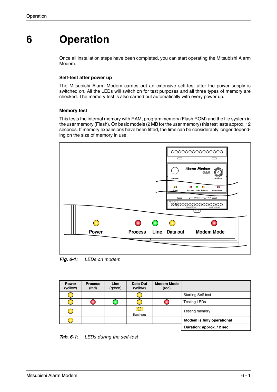
Fig. 6-1 LEDs on modem
Self-test after power up
6 Operation
Memory test
Mitsubishi Alarm Modem is operational
Line-LED when functioning correctly only GM series
MITSUBISHI ELECTRIC
7.3 Loading projects remotely on the MAM
7 Configuration and projects
7.1 Initial configuration
7.2 Loading projects in the MAM
7.4.4 PIN incorrect, MAM not logged in
7.4.5 SIM card disabled, entry of the SUPER PIN
7.4.6 SIM Card Service Center
7.4.3 PIN OK, no network, MAM not logged in
7.5.3 TiXML Mode
7.5.1 Alarm Editor MX-MAE activates the correct mode
7.5.2 Using MAM without MX-MAE
7.5 Operating modes Modem Mode and TiXML Mode
Deactivating Modem Mode, activating TiXML Mode
7.5.6 Sending commands to the MAM
7.5.5 Activating/deactivating Modem Mode
Activating Modem Mode
8 Software
8.1 MX Mitsubishi Alarm Editor MX-MAE
8.2 Secure Login Access Protection
Fig. 8-1 Mitsubishi Alarm Editor MX-MAE
MITSUBISHI ELECTRIC
8.3 Remote Access
9 Communication with a PLC
9.1 PLC driver in the Mitsubishi Alarm Modem
Tab. 10-1 Main functions
10.1 Technical data of the MAM series
10 Appendix
Main functions
Tab. 10-5 Technical specifications AM series
Technical specifications GM series
Tab. 10-3 Technical specifications GM series
Technical specifications AM series
General Data
Tab. 10-7 General data
MITSUBISHI ELECTRIC
Tab. 10-9 LEDs in the event of faults
10.2 LEDs, Reset, Update, Error Diagnostics
10.2.2 LEDs in the event of faults only GM series
10.2.3 Factory Reset
Tab. 10-10 LEDs during Firmware-Update
10.2.4 Firmware-Update
LEDs during factory reset and restart
Tab. 10-11 LEDs during Factory Reset and restart
Pin assignment
10.3 Accessories
Tab. 10-12 Accessories
10.4 Mobile networks in Europe - USA - worldwide
10 with Alarm -30 2x V Rs23 Modem DC,max 2+ GSM 6 .0 I/Os .7A
10.5 Dimensions
Fig. 10-1 Dimensions GM series
10.5.1 GM series
Modem Mode
Fig. 10-2 Dimensions AM series
10.5.2 AM series
10 with Alarm -30 2x V Rs23 Modem DC,max 2+ 56k 6 .0 I/Os .7A
MAM-GM20
10.6.1 MAM-GMx Mitsubishi Alarm Modems GSM with RS232 and RS485
10.6 Terminals
MAM-GM6
MAM-AM20
10.6.2 MAM-AMx Mitsubishi Alarm Modems 56k with RS232 and RS485
Abb. 10-4 MAM-AMx Mitsubishi Alarm Modems 56k with RS232 and RS485
MAM-AM6
Index
Index
Mitsubishi Alarm Modem
MIDDLE EAST REPRESENTATIVES
MITSUBISHI ELECTRIC
MITSUBISHI ELECTRIC INDUSTRIAL AUTOMATION
HEADQUARTERS