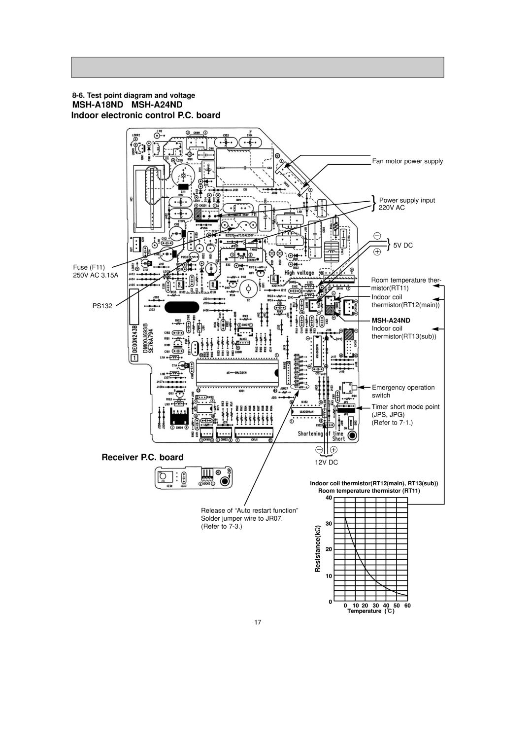
MSH-A18ND MSH-A24ND
Indoor electronic control P.C. board
Fuse (F11) 250V AC 3.15A
PS132
Receiver P.C. board
Release of “Auto restart function” Solder jumper wire to JR07. (Refer to
Fan motor power supply
}Power supply input 220V AC
+} 5V DC
Room temperature ther- mistor(RT11) ![]()
![]()
![]() Indoor coil
Indoor coil ![]() thermistor(RT12(main))
thermistor(RT12(main))
![]()
Indoor coil ![]() thermistor(RT13(sub))
thermistor(RT13(sub))
![]() Emergency operation switch
Emergency operation switch
![]() Timer short mode point (JPS, JPG)
Timer short mode point (JPS, JPG)
(Refer to
+
}
12V DC
Indoor coil thermistor(RT12(main), RT13(sub)) Room temperature thermistor (RT11)
Resistance(k")
17