10
SW4 SW3 SW2 |
| CN32 CN52 CN51 CN41 CN23 CN24 CN25 CN27 CN22 | |||||||
|
|
|
|
|
|
|
|
| (Green)(Yellow) (White) (Red) (Green) |
|
| (White) | (Green) | (White) | (White) | ||||
1 | LED1 |
|
|
| LED2 | ||||
2(Red)
3
4 CN42
|
|
|
|
|
|
|
|
|
|
|
|
|
|
|
|
| (Red) |
|
| (Red) | (White) | (Black) | (White) |
| (White) |
|
|
| (Red) | ||||||||
|
|
|
|
|
|
|
|
|
|
|
|
|
|
|
|
| CN81 |
|
| CN20 | CN21 | CN29 | CN31 |
| CN60 |
|
|
| CN3T | ||||||||
A.B. |
|
| 1 | 2 | 3 | 4 | 5 | 6 |
| 8 | 7 | 6 | 5 | 4 | 3 | 2 | 1 | 2 | 1 | 2 | 1 | 2 | 1 | 2 | 1 | 6 | 5 | 4 | 3 | 2 | 1 | 3 | 1 | ||||
|
|
|
|
|
|
|
|
| |||||||||||||||||||||||||||||
|
| SWA SWC SW5 |
|
| CN62 |
|
|
|
|
|
|
|
|
|
|
|
|
|
|
|
|
|
|
|
|
|
|
|
|
|
| ||||||
|
|
|
|
|
|
|
|
| (White) |
| 8 |
|
|
|
|
|
|
|
|
|
|
|
|
|
|
|
|
|
|
|
|
|
| T | |||
|
|
|
| SW1 | SW7 |
|
|
|
|
| (White) |
|
|
|
|
|
|
|
|
|
|
|
|
|
|
|
|
|
|
|
|
|
| ||||
|
|
|
|
|
|
|
|
| 7 |
|
|
|
|
|
|
|
|
|
|
|
|
|
|
|
|
|
|
|
|
|
|
| |||||
|
|
|
|
|
|
|
|
|
|
|
| CN82 | 6 |
|
|
|
|
|
|
|
|
|
|
|
|
| CN31 |
|
|
|
|
|
|
|
| ||
|
|
| 0 |
|
|
| 0 |
|
|
|
| 0 |
| 5 |
|
|
|
|
|
|
|
|
|
|
|
|
|
|
|
|
|
|
|
|
| ||
E | F |
| 1 |
| 9 | 1 |
| 9 | 1 | 4 |
|
|
|
|
|
|
|
|
|
|
|
|
|
|
|
|
|
|
|
|
|
|
| ||||
|
| 2 |
|
|
|
|
|
| 3 |
|
|
|
|
|
|
|
|
|
|
|
|
|
|
|
|
|
|
|
|
|
|
| |||||
D |
|
|
|
| 3 | 8 |
|
| 2 | 8 |
| 2 |
|
|
|
|
|
|
|
|
|
|
|
|
| 3 | 1 |
|
|
|
|
|
|
|
| ||
|
|
|
|
|
|
| 2 |
|
|
|
|
|
|
|
|
|
|
|
|
|
|
|
|
|
|
|
|
| |||||||||
C |
|
|
|
| 4 | 7 |
|
| 3 |
| 7 |
| 3 |
|
|
|
|
|
|
|
|
|
|
|
|
|
|
|
|
|
|
|
|
| |||
B | 9 |
|
| 5 |
| 4 |
|
| 1 |
|
|
|
|
|
|
|
|
|
|
|
|
|
|
|
|
|
|
|
|
|
|
| |||||
|
|
| 6 |
|
|
|
|
|
| 4 |
|
|
|
|
|
|
|
|
|
|
|
|
|
|
|
|
|
|
|
|
|
|
|
| |||
A |
| 8 | 7 | 6 | 5 |
|
|
| 6 |
|
|
|
|
|
|
|
|
|
|
|
|
|
|
|
|
|
|
|
|
|
|
|
|
| |||
|
|
|
|
|
|
|
|
| 5 |
|
|
|
|
|
|
|
|
|
|
|
|
|
|
|
|
|
|
|
|
|
|
|
|
| |||
SW14 |
| SW12 |
| SW11 |
|
|
|
|
|
|
|
|
|
|
|
|
|
|
|
|
|
|
|
|
|
|
|
| |||||||||
(Connection No.) | (2nd digit) |
| (1st digit) |
|
|
|
|
|
|
|
|
|
|
|
|
|
|
|
|
|
|
|
|
|
|
|
| ||||||||||
|
|
|
|
|
|
|
|
|
|
|
|
|
|
|
|
|
|
|
|
| TH21 |
| TH22 |
| TH23 |
|
| DS |
|
|
| LEV |
|
|
|
| |
|
|
|
|
|
|
|
|
|
|
|
|
|
|
|
|
|
|
|
|
|
|
|
|
|
|
|
|
|
|
|
|
|
|
| |||
![]() NOTE 1
NOTE 1
INSIDE SECTION OF CONTROL BOX
I.B.
|
|
| FAN2 | (Yellow) 5 | 3 | 1 |
|
|
|
| TB15 (TRANSMISSION TERMINAL BED) | ||
|
|
|
|
|
|
|
|
|
|
| |||
|
|
|
|
|
|
|
|
|
| (Blue) | 3 | 2 | TO MA REMOTE |
|
| X01 |
| X03 |
|
|
| ZNR | CN3A | ||||
|
|
|
|
|
| 1 | 1 | ||||||
|
|
|
|
|
|
| CONTROLLER | ||||||
|
|
|
|
| FAN CON |
|
|
|
| ||||
|
|
|
|
|
| (Blue) | 2 |
|
| ||||
|
|
|
|
|
|
|
|
|
| CN2M | TB5 (TRANSMISSION TERMINAL BED) | ||
|
|
|
|
|
|
|
|
|
| 1 | |||
|
|
|
|
|
|
|
|
|
| F | |||
|
|
|
|
|
|
|
|
|
|
| S(SHIELD) |
| |
|
|
|
|
|
|
|
| (White) (6.3AAC250VT) |
|
| |||
| (White) |
| (Blue) |
| (Green) |
|
|
| M2 | TO OUTDOOR UNIT | |||
| CNT |
| CNP |
| CNV |
|
| FAN3 | CND (Red) |
| M1 | BC CONTROLLER | |
3 | 1 | 3 | 1 | 3 | 1 | 5 | 3 | 1 | 3 | 1 |
| S.B. | REMOTE CONTROLLER |
|
| ||||||||||||
|
|
|
|
|
|
|
|
|
| ZNR1 CN1 | 1 (Yellow) |
| |
|
|
|
|
|
|
| C |
|
| DSA1 |
| 3 | TO NEXT INDOOR UNIT |
|
|
|
|
|
|
|
|
|
|
| L1TB2 |
| |
|
|
|
|
|
|
|
|
|
|
|
| PULL BOX | |
|
|
|
|
|
|
|
|
|
|
|
|
| |
|
|
|
|
|
|
|
|
|
|
|
| L2 |
|
|
|
|
|
|
|
|
|
|
| F2 | G |
| |
|
|
|
|
|
|
|
|
|
| (AC250V5A F ) | FUSE(15A) | ||
|
|
|
|
|
|
|
|
|
|
|
|
| BREAKER(15A) |
(White) | 3 | 2 1 | (White) | 4 | 2 | 1 |
|
|
|
|
| ||
|
|
|
|
|
|
|
|
|
| A |
|
|
|
|
|
|
|
|
|
|
|
| A connector is |
| TO DUCT | POWER SUPPLY | |
|
|
|
|
|
|
|
|
| attached to the | ||||
|
|
|
|
|
|
|
|
| drain lift up |
|
| 208V/230V 60Hz | |
|
| DP |
|
| MF |
| mechanism, |
|
|
| |||
| which is an | |
NOTE 1 | optional part. | |
NOTE 1,2 | ||
|
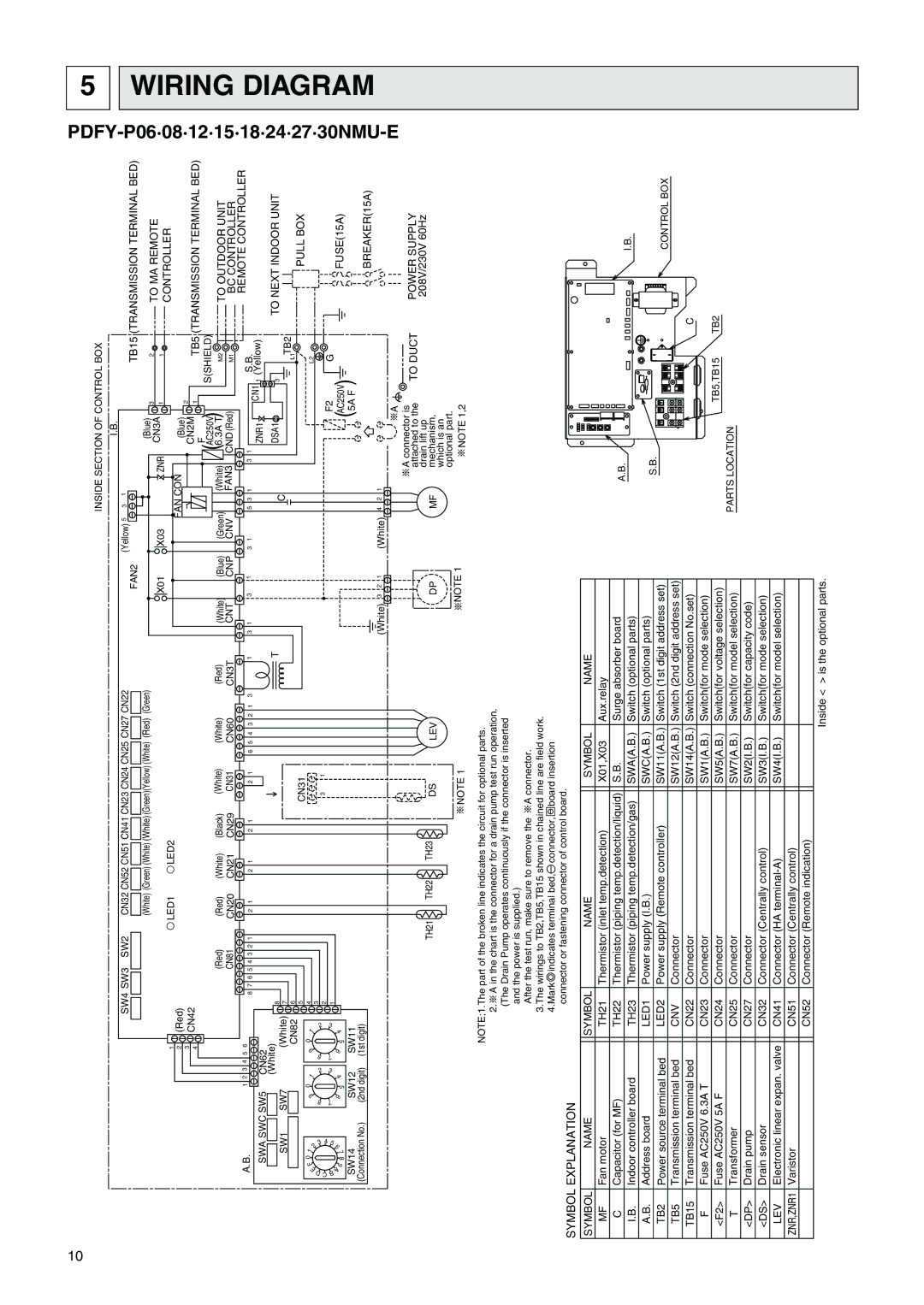
5 WIRING DIAGRAM
NOTE;1.The part of the broken line indicates the circuit for optional parts.
2.![]() A in the chart is the connector for a drain pump test run operation. (The Drain Pump operates continuously if the connector is inserted and the power is supplied.)
A in the chart is the connector for a drain pump test run operation. (The Drain Pump operates continuously if the connector is inserted and the power is supplied.)
After the test run, make sure to remove the ![]() A connector.
A connector.
3.The wirings to TB2,TB5,TB15 shown in chained line are field work. 4.Mark indicates terminal bed, connector, board insertion
connector or fastening connector of control board.
SYMBOL EXPLANATION
SYMBOL | NAME |
| SYMBOL | NAME |
| SYMBOL | NAME |
MF | Fan motor |
| TH21 | Thermistor (inlet temp.detection) |
| X01,X03 | Aux.relay |
C | Capacitor (for MF) |
| TH22 | Thermistor (piping temp.detection/liquid) |
| S.B. | Surge absorber board |
I.B. | Indoor controller board |
| TH23 | Thermistor (piping temp.detection/gas) |
| SWA(A.B.) | Switch (optional parts) |
A.B. | Address board |
| LED1 | Power supply (I.B.) |
| SWC(A.B.) | Switch (optional parts) |
TB2 | Power source terminal bed |
| LED2 | Power supply (Remote controller) |
| SW11(A.B.) | Switch (1st digit address set) |
TB5 | Transmission terminal bed |
| CNV | Connector |
| SW12(A.B.) | Switch (2nd digit address set) |
TB15 | Transmission terminal bed |
| CN22 | Connector |
| SW14(A.B.) | Switch (connection No.set) |
F | Fuse AC250V 6.3A T |
| CN23 | Connector |
| SW1(A.B.) | Switch(for mode selection) |
<F2> | Fuse AC250V 5A F |
| CN24 | Connector |
| SW5(A.B.) | Switch(for voltage selection) |
T | Transformer |
| CN25 | Connector |
| SW7(A.B.) | Switch(for model selection) |
<DP> | Drain pump |
| CN27 | Connector |
| SW2(I.B.) | Switch(for capacity code) |
<DS> | Drain sensor |
| CN32 | Connector (Centrally control) |
| SW3(I.B.) | Switch(for mode selection) |
LEV | Electronic linear expan. valve |
| CN41 | Connector (HA |
| SW4(I.B.) | Switch(for model selection) |
ZNR,ZNR1 | Varistor |
| CN51 | Connector (Centrally control) |
|
|
|
|
|
| CN52 | Connector (Remote indication) |
|
|
|
|
|
|
|
|
| Inside < > is the optional parts. | |
A.B.
I.B.
S.B.
CONTROL BOX
C
TB5,TB15 TB2
PARTS LOCATION