8 
 DISASSEMBLY PROCEDURE
Be careful removing heavy parts.
OPERATING PROCEDURE | PHOTOS |
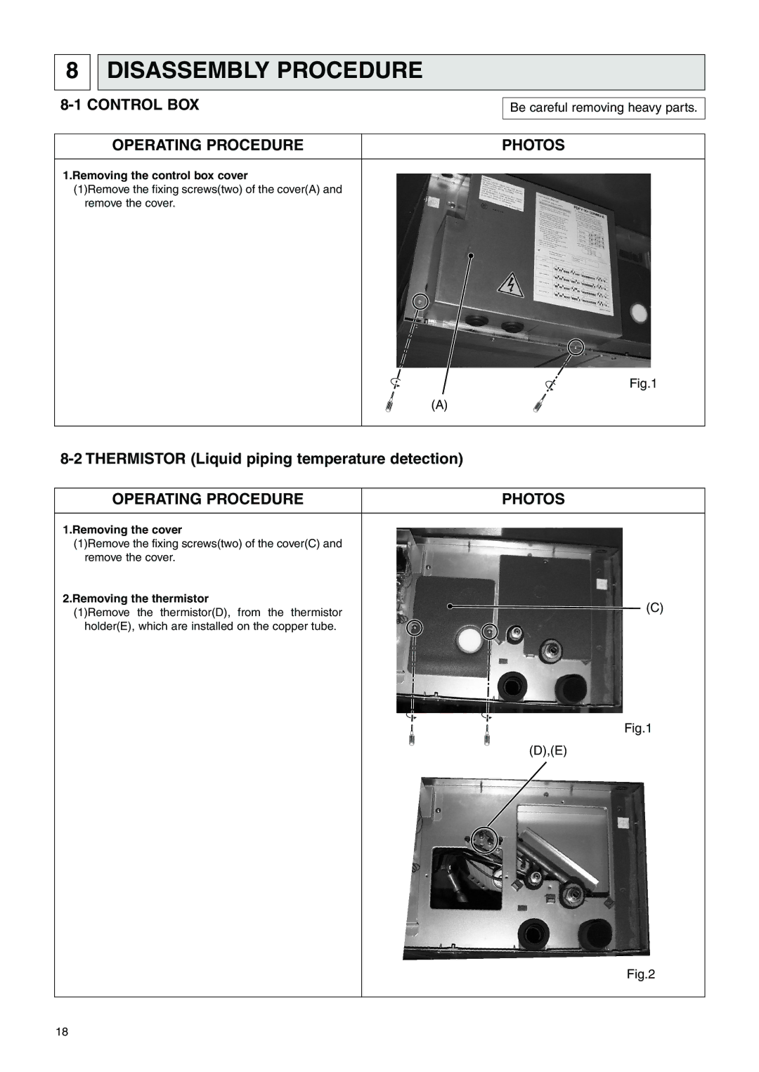
1.Removing the control box cover
(1)Remove the fixing screws(two) of the cover(A) and remove the cover.
Fig.1
(A)
OPERATING PROCEDURE | PHOTOS |
1.Removing the cover
(1)Remove the fixing screws(two) of the cover(C) and remove the cover.
2.Removing the thermistor | (C) | |
(1)Remove the thermistor(D), from the thermistor | ||
| ||
holder(E), which are installed on the copper tube. |
|
Fig.1
(D),(E)
Fig.2
18