8
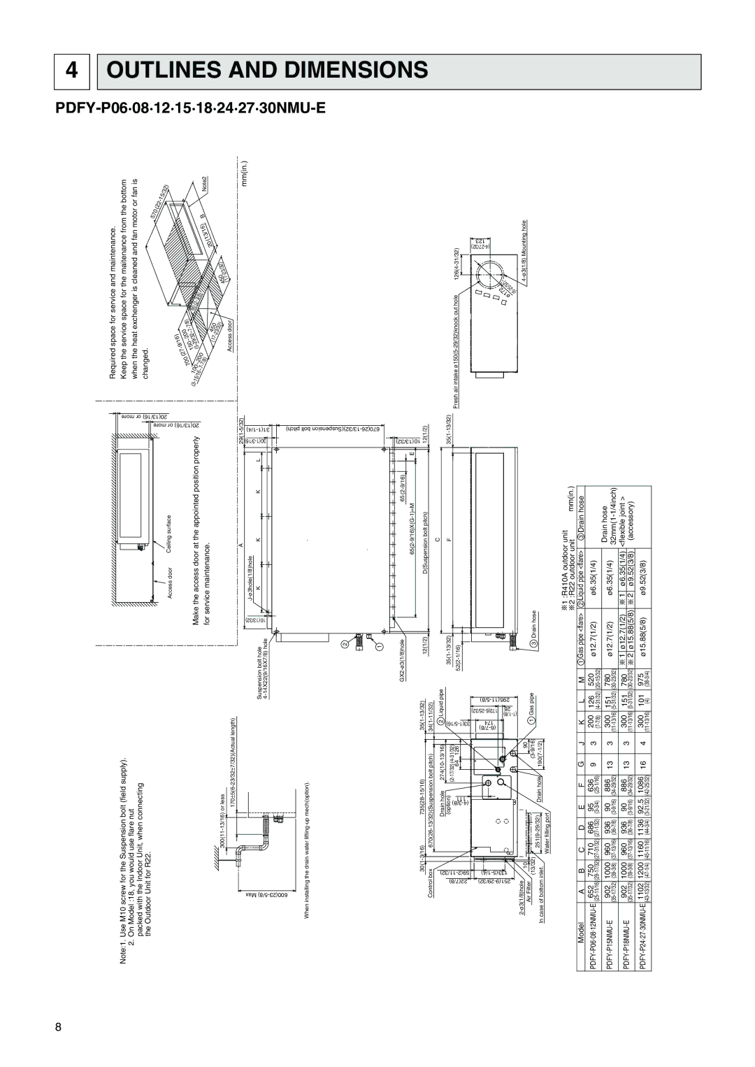
Note:1. Use M10 screw for the Suspension bolt (field supply).
2.On Model :18, you would use flare nut packed with the Indoor Unit, when connecting the Outdoor Unit for R22.
Access door | Ceiling surface |
Make the access door at the appointed position properly for service maintenance.
more | 20(13/16) or more |
20(13/16) or |
|
Required space for service and maintenance.
Keep the service space for the maitenance from the bottom when the heat exchenger is cleaned and fan motor or fan is changed.
570
(22 - 15/32)
|
| (27 | (5 |
| 9/16) |
|
|
|
|
|
|
|
|
|
15/16~7100~200 |
| 150~200 |
|
|
|
|
|
|
|
|
| |||
| 700 |
| - |
| 29/32~7 | - | 7/8) |
|
|
|
|
|
| |
(3 |
|
| - | 60 |
|
|
|
|
| |||||
| - |
|
|
|
|
|
|
|
|
| ||||
- |
|
|
|
|
|
|
| (2 |
|
|
|
|
| |
|
|
|
| - |
|
| - |
| 20 | (13/16) |
|
| ||
|
|
|
|
|
|
|
| 3/8) |
|
|
| B | Note2 | |
| 7/8) |
|
|
|
|
|
|
|
|
|
|
| ||
|
|
|
|
| (17 | 450 |
|
|
|
|
|
| ||
|
|
|
|
| 23/32) | (17 |
| 23/32) |
|
|
| |||
|
|
|
|
|
|
|
|
|
|
|
|
| ||
|
|
|
|
|
|
|
|
| 450 | - |
|
|
|
|
Access door
4 OUTLINES
When installing the drain water
|
|
|
| |||||
Control box | ||||||||
22(7/8) |
|
| (4 | |||||
|
|
| Drain hole | |||||
|
|
|
| (option) | ||||
|
|
|
| 3/8)- |
| 64 | 126 | |
|
|
|
| 111 |
| |||
|
|
|
|
|
|
| ||
|
|
|
|
|
| |||
10 |
|
|
|
|
| 90 | ||
Air Filter |
|
|
|
|
| |||
(13/32) |
|
|
|
|
| |||
| Drain hole |
| ||||||
In case of bottom inlet. | ||||||||
|
| |||||||
Water filling port
Suspension bolt hole | (13/32) | |
10 | ||
|
|
|
| 2 |
|
|
| 1 |
|
|
| |
12(1/2) | |||
| |||
|
| ||
2 | Liquid pipe | ||
5/16)- |
|
| |
|
|
| |
33(1 |
|
| |
| |||
| |||
1 | Gas pipe | 3 Drain hose | |
|
|
| |
A
KKK
65
D(Suspension bolt pitch)
C
F
L
|
E | (13/32) |
| 10 |
12(1/2)
mm(in.)
Fresh air intake |
172 | |
ø | |
| (6 |
AND DIMENSIONS
|
|
|
|
|
|
|
|
|
|
|
|
|
| 1 :R410A outdoor unit | ||||
|
|
|
|
|
|
|
|
|
|
|
|
|
| 2 :R22 outdoor unit | mm(in.) | |||
Model | A | B | C | D | E | F | G | J | K | L | M | 1 Gas pipe <flare> | 2 Liquid pipe <flare> |
| 3 Drain hose | |||
652 | 750 | 710 | 686 | 95 | 636 | 9 | 3 | 200 | 126 | 520 | ø12.7(1/2) | ø6.35(1/4) |
|
| ||||
|
|
|
|
|
|
| Drain hose | |||||||||||
902 | 1000 | 960 | 936 | 90 | 886 | 13 | 3 | 300 | 151 | 780 | ø12.7(1/2) | ø6.35(1/4) | ||||||
902 | 1000 | 960 | 936 | 90 | 886 | 13 | 3 | 300 | 151 | 780 | 1 | ø12.7(1/2) | 1 | ø6.35(1/4) <flexible joint > | ||||
2 | ø15.88(5/8) | 2 | ø9.52(3/8) | (accessory) | ||||||||||||||
1102 1200 1160 1136 | 92.5 | 1086 | 16 | 4 | 300 | 101 | 975 | ø15.88(5/8) | ø9.52(3/8) |
|
| |||||||
|
|
| (4) |
|
|
|
|
|
| |||||||||
