6 
 REFRIGERANT SYSTEM DIAGRAM
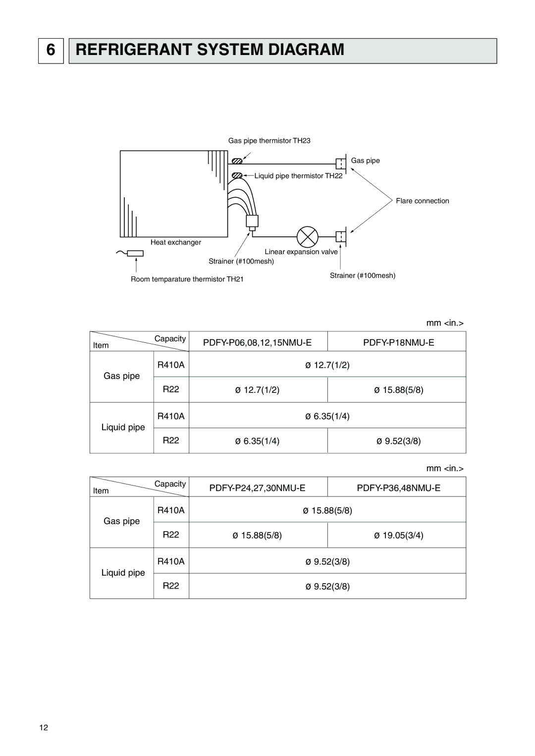
Gas pipe thermistor TH23
Gas pipe
Liquid pipe thermistor TH22
Flare connection
Heat exchanger
| Linear expansion valve |
Strainer (#100mesh) | |
Room temparature thermistor TH21 | Strainer (#100mesh) |
| |
mm <in.>
Capacity | ||
Item | ||
R410A | ø 12.7(1/2) |
|
Gas pipe |
|
|
R22 | ø 12.7(1/2) | ø 15.88(5/8) |
R410A | ø 6.35(1/4) |
|
Liquid pipe |
|
|
R22 | ø 6.35(1/4) | ø 9.52(3/8) |
mm <in.>
Capacity | ||
Item | ||
R410A | ø 15.88(5/8) |
|
Gas pipe |
|
|
R22 | ø 15.88(5/8) | ø 19.05(3/4) |
R410A | ø 9.52(3/8) |
|
Liquid pipe |
|
|
R22 | ø 9.52(3/8) |
|
12