Owner’s Guide
Stand Requirement
FCC Declaration of Conformity
Contents
Special Features
Ieee 1394 Devices and NetCommand Controlled Recordings
TV Menu Screen Operations
Important Safeguards
Important Safeguards
Our Thanks
Mitsubishi Digital Electronics America, Inc
Television Overview
TV Accessories Special Features Front Control Panel
Back Panel
TV Accessories
Special Features
System Reset
Indicators
Reset
Front Control Panel
Media Card Slots and Ieee 1394 Input/Output
Front Panel Inputs and Media Card Slots
Input
Back Panel
CableCARD Slot
Input-DTV
Component-1, -2 Inputs
IR Emitter-NetCommand
PC Input and Audio
DTV Link/IEEE1394
DVI Analog Audio
Page
Connecting
Connecting External Devices & NetCommand Setup
Chart
Wall Outlet Cable
Connecting a Wall Outlet Cable or Cable Box
Cable Box
Using a CableCARD
CableCARD Technology
Connecting a Lead Antenna or Separate UHF and VHF Antenna
Separate UHF and VHF Antenna
For antennas with twin flat lead
For cable or antenna with coaxial lead
Connecting a VCR to an Antenna or Wall Outlet Cable
Connecting a Cable Box to a VCR Audio & Video
Cable Box Back panel
Connecting an A/V receiver
Connecting a DVD Player with Component
DTV Connectors and Adaptors
DTV Receiver with Component Video
DTV Receiver with RGB, HV Video
Connecting a DTV Receiver with RGB, HV Video
DTV Receiver to TV Back Panel
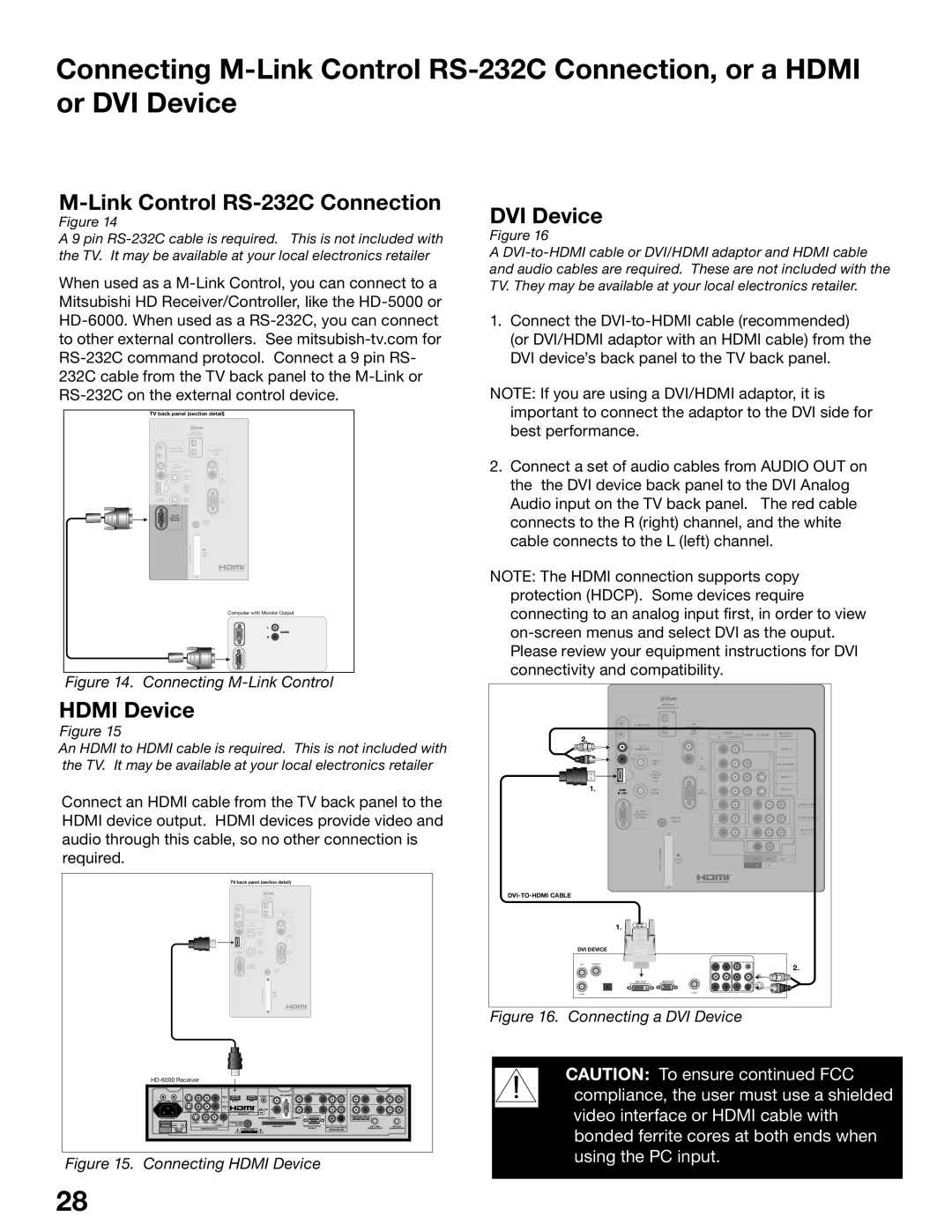
Link Control RS-232C Connection
Link
Connecting the IR Emitter NetCommand
Quadruple IR Emitter cable is included with the TV
Connecting Compatible Ieee 1394 Devices
When Connecting Ieee 1394 Devices
Digital Video Signals
Digital Audio Signals
Pin Style vs -Pin Style Connectors
Connection Styles
Direct Device-To-Device Style
Hub Connection Style
Connecting Helpful Hints
NetCommand Setup and Editing
Using the Remote Control with NetCommand
NetCommand Pre-Memorized Devices
Remote Control Functions Overview
Overview
Remote Control FunctionsOperation and Care, Sleep Timer
For Best Results from the Remote Control
Installing the Batteries
Setting the Sleep Timer
NetCommand Setup On Screen Buttons
Remote Control Buttons
3D Graphical Menu System
NetCommand Initial Setup
NetCommand Information Screen
Device Setup Screen
Welcome Screen
Review Screen
Review screen
Receiver Screen
Edit NetCommand, Add an A/V Receiver
Receiver Inputs
Receiver Input Learn Screen
Receiver Learn Screen
Name Screen
Monitor Out to AVR Screen
Edit NetCommand Screen
Edit NetCommand, Add Devices
Add Screen
Device Screen
Edit NetCommand Add Devices
Device Learn Screen
Device Advanced Learn Screen
Connection for Device Screen
VCR for Recordings Screen
RF Connection for Cable Screen
Input-DTV Connection Screen
IR Code for Device Screen
Change Device Screen
Edit NetCommand, Change or Delete Devices, Finish Screen
Delete Device Screen
Device Selection Menu
Ieee 1394 Devices NetCommand Controlled Recordings
PC Viewing
Ieee 1394 Devices and NetCommand Control
Adding Ieee 1394 Devices Automatically
Adding Ieee 1394 Devices Automatically
New 1394 Device Screen
Name for 1394 Device Screen
Ieee 1394 Device Type Screen
Connection Screen
Device Selection Menu
Power On/Off Devices
PIP Device Selection Menu
Using the Device Menu Button to Display Menus
Device Menu
IR Controlled Devices
CableCARD Menu
Using the Guide Button to Display ChannelView and Menus
Guide and the Device Selection Menu
Guide and the Record To Menu
Guide and ChannelView
Time-Delayed Recording
Setting up Recordings
Recording Now
Setting up a Peer-to-Peer Connection
Cancel Current Recordings
Canceling a Peer-to-Peer Connection
Record List, Peer-to-Peer Connections
Using TV Disc & A/V Discs
TV Disc & A/V Disc Track List Screen
TV Disc or A/V Disc Search
Archiving TV Disc Digital Recordings
Copy-Protected Material
Direct VCR Recording from an Antenna or Cable Source
Restrictions for Traditional VCRs
PC Viewing
PC Input
MediaCommand and Media Card Playback
Media Card Slots
Inserting a media card
Don’t pull the media card out while it is playing
Media Command and Media Card Playback
TV Menu Screen Operations
Main menu, Setup selected
Main Menu Choices
Setup Menu
Language
Color Balance
TV Pause
Controlling the TV Pause Features
Software Version
NetCommand Menu
Antenna Menu
Memorize
Prefer Digital
Channel
Antenna Menu, SuperQuickView SQV
SQV SuperQuickView
Time Menu
Captions Menu Analog and Digital Captions
Captions Menu, Customizing Digital Settings
Chip Lock Menu
Chip Lock Menu Overview
Selecting a Passcode from the V-Chip Lock Menu
Front Button Lock
Using the Passcode from the V-Chip Lock Menu
Using V-Chip with Program Ratings
Using the V-Chip from the Remote Control
Chip Signal Information
Content Categories
Chip Rating Guidelines
TV Ratings
AudioVideo Menu
Setting Descriptions Audio
Analog and Digital Audio Setting
Analog Only Audio Settings
Digital Only Audio Settings
Video Settings
Setting Descriptions Video
For a Currently Viewed PC
Operation of PIP and POP
Page
Additional Information
Warranty
Index
Display Formats
Signals and Formats Definitions
DVD Definitions
Original Signal
TV Display Formats
PC Display Formats
Device Control with Net Command
NetCommand Compatible Traditional Devices Analog
When an Ieee 1394 Device is Viewed or Played
Ieee 1394 Devices
Bypassing the V-Chip Lock
Appendix a Bypassing the V-Chip Lock
Bypassing Front Button Lock
This page intentionally blank
TV Specifications
Appendix B Specifications
Inputs
Outputs
Appendix CRemote Control Programming Codes
Programming the Remote to Control NetCommand A/V Products
Appendix C Remote Control Programming Codes
DVD Players
Cable Boxes and Satellite Receivers
Receivers
Mitsubishi A/V Receivers
Mitsubishi CD Players Not all functions for all models
Appendix D On Screen Information Displays
Appendix E NetCommand Specialized Device Keys
Screen Remote Checkbox Name
Appendix F Cleaning and Service
To Install the Diamond Shield
Appendix G Diamond Shield Removal
To Remove the Diamond Shield
For further assistance, call 800
Appendix H Filter Cleaning
Appendix H Lamp Cartridge Replacement
Lamp Life
100
Replacing the Lamp Cartridge
Problem Possible Solution
Troubleshooting
101
102
103
104
Using The System Reset Button
105
Additional Information
106
Index
107
108
Icon Order, Viewing, Changing 67 IEEE1394
Mitsubishi TV Software
109
Mitsubishi DLP Projection Television Limited Warranty
110
This Warranty does not Cover
111
MDEAservice@mdea.com
Website