Owner’s Guide
Page
Contents
Contents
Important Safeguards
Safeguards
Important Notes
Television Overview
Chapter
OUR Promise
Thank You for Your Purchase
Your New TV /Special Features
Special Features
Unpacking Your New TV
Unpacking
Reset
Timer
Front Control Panel
Format
WS-48315, WS-55315, WS-65315, WS-65315A Back Panel
Side Panel Input/Output for WT-42315
Important Notes
Connections
Connecting a DTV Receiver Connecting MonitorLink/DVI
Outlet Cable
Connecting an Antenna or Wall Outlet Cable
Separate UHF and VHF Antennas
For antenna with twin flat leads
Connecting an
Connecting an Antenna to a Cable Box or VCR
To a Cable Box or VCR
Cable Box
Connect three coaxial cables as follows
Composite Video with Audio or S-Video with AudioRecommended
Connecting an Audio Receiver
Stereo Audio System
Receiver
Connecting
Connecting a DVD Player or Other S-Video Device
Or Other
DVD Player
DTV Connectors and Adaptors
Connecting a DTV Receiver
DTV Receiver
DTV Receiver with Component Video Connections Recommended
Green Blue Pb/B Red Pr/R
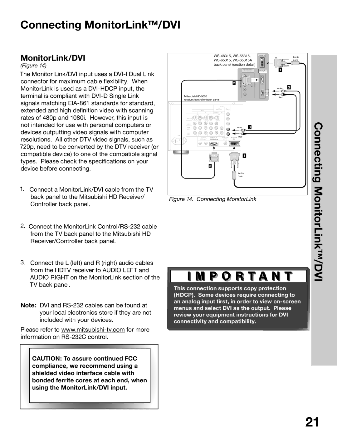
Connecting MonitorLink/DVI
MonitorLink/DVI
MonitorLink/DVI
How Connections Affect
PIP Picture-In-Picture and POP Picture-Outside-Picture
Ant-A Ant-B
Remote Control Functions
Overview
Remote Control Functions Overview of the TV Layer Buttons
Operating the Remote Control
Remote Control Functions Care and Operation
For Best Results from the Remote Control
Operation
Setting the Sleep Timer
Sleep Timer
Canceling the Sleep Timer
Channel Selection
Use of the Remote Control with Other A/V Products
Remote Control with Other A/V Products
Use
Use of the Remote Control with Other A/V Products
Remote Control Functions Special Functions
Operation of PIP and POP
Activating the PIP and POP
Important Notes
Menu Screen Operations
Menu System
System
Menu
Main Menu Screens Overview
Setup Menu
Captions Menu
Channel Edit Menu
Advanced Features Menu
AUDIO/VIDEO Settings Menu
Chip Lock Menu
Memorize Channels
Memorize Menu
Input Assignment Menu
Setup Menu Manually Setting the Clock
Clock Setting Manual
Set Day
Clock Setting Auto
Setup Menu Automatically Setting the Clock
Time Zone
Daylight Savings Time
Setup Menu Language, Front Button Lock WT-42315
Language
Front Button Lock for WT-42315
Setup Menu Energy Mode
WS-65315A Energy Mode
WS-48315, WS-55315, WS-65315
Captions Menu Overview
Captions Menu Closed Captions, Background Color
Closed Captions
CC Background
Channel Edit Menu Antenna, Channel Selection
Antenna
Channel
Channel Edit Menu
Channel Edit Menu Memory, Name Selection
Memory, Name Selection
Memory
Menu Using SQV
Channel Edit Menu Using SQV Super Quick View
Using The Menu Screen
Using The Remote Control
Chip Signal Information
Chip Lock Menu Overview
Menu Overview
Chip Menu Setting Up and Using V-Chip Lock Passcode
Setting Up the V-CHIP Lock Passcode
Entering the Passcode
Allowing or Blocking by Ratings
Chip Start Time and V-CHIP Stop Time
Lock by Time, Lock Time, and Unlock Time
Lock by Time
Front Button Lock
Selecting V-Chip Rating Menu
Chip Start Time Chip Stop Time
Allowing or Blocking Ratings, Lock by Time
Color Balance Menu
Reset Color
Auto Color Correction
PerfectColor
Advanced Features Menu TIMER, Timer Menu, and Set Time
Timer menu
Set Time
Input
Advanced Features Menu Set Day, Input, and Channel
Convergence Menu
Advanced Features Menu Convergence
Convergence Screen
Advanced Convergence
Black Enhancement
Video Mute
Settings Menu Overview
AUDIO/VIDEO Settings Menu Overview
Audio Settings
AUDIO/VIDEO Setting Descriptions Audio
Video Settings
AUDIO/VIDEO Setting Descriptions Video
This page intentionally blank
Available On-Screen Format Sizes Operation of PIP and POP
PIP/POP Operations
Available On-Screen Format Sizes
Widescreen Picture 480i/480p
Operation of PIP and POP
Appendix a Bypassing V-Chip Lock
Appendix a Bypassing the V-Chip Lock
Bypassing the V-Chip Lock
This page intentionally blank
Appendix B High Definition Input Connection Compatibility
Appendix C Remote Control Programming Codes
Receivers
Cable Box DVD Players
DBS/DTV
Satellite Receivers VCRs
Cleaning
Appendix D Cleaning and Service
Service
General Cleaning Warnings
Installation
Page
Terminal Cover
Terminal Cover Ventilation for Model WT-42315
Ventilation for Model WT-42315
Stand Requirement
Index
Index
Lock by Time for
Problem Possible Solution
Troubleshooting
Page
Mitsubishi Digital Electronics America, Inc 871D404B10