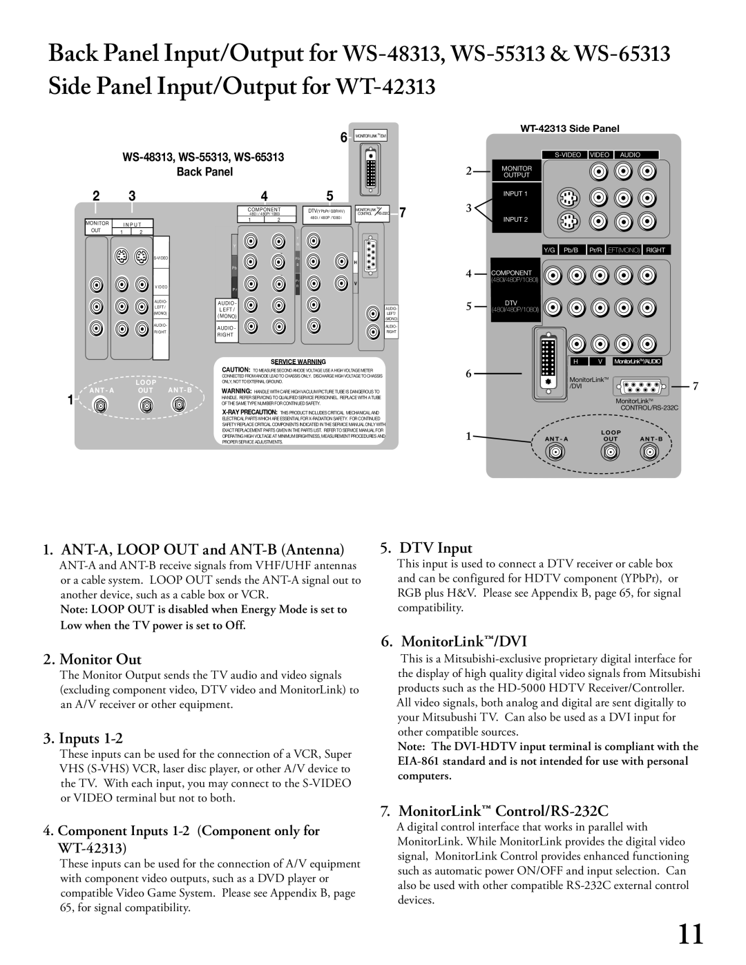
Back Panel Input/Output for
WS-48313, WS-55313, WS-65313
Back Panel
6MONITORLINKTM/DVI
WT-42313 Side Panel
S-VIDEO VIDEO AUDIO
2MONITOR OUTPUT
2
MONITOR
OUT
3
I N P U T
12
V IDEO
AUDIO- LEFT / (MONO)
AUDIO-
RIGHT
Y
Pb
P r
AUDIO - LEFT /
AUDIO - RIGHT
4
COMPONENT 480i / 480P/ 1080i
12
Y
G
Pb
B
P r
R
5
DTV(YPbPr/ GBRHV) 480i / 480P /1080i
MONITORLINKTM7 CONTROL
H
V
AUDIO-
LEFT/
(MONO)
AUDIO-
RIGHT
INPUT 1
3 ![]()
INPUT 2
Y/G Pb/B | Pr/R LEFT(MONO) RIGHT |
4COMPONENT (480I/480P/1080I)
5DTV (480I/480P/1080I)
|
|
|
| SERVICE WARNING |
|
|
|
| CAUTION: TO MEASURE SECOND ANODE VOLTAGE USE A HIGH VOLTAGE METER |
|
| LOOP |
| CONNECTED FROM ANODE LEAD TO CHASSIS ONLY. DISCHARGE HIGH VOLTAGE TO CHASSIS |
| ANT - A | ANT- B | ONLY, NOT TO EXTERNAL GROUND. | |
1 | OUT | WARNING: HANDLE WITH CARE HIGH VACUUM PICTURE TUBE IS DANGEROUS TO | ||
|
|
| HANDLE. REFER SERVICING TO QUALIFIED SERVICE PERSONNEL. REPLACE WITH A TUBE | |
|
|
| OF THE SAME TYPE NUMBER FOR CONTINUED SAFETY. |
ELECTRICAL PARTS WHICH ARE ESSENTIAL FOR
SAFETY REPLACE CRITICAL COMPONENTS INDICATED IN THE SERVICE MANUAL ONLY WITH
EXACT REPLACEMENT PARTS GIVEN IN THE PARTS LIST. REFER TO SERVICE MANUAL FOR
OPERATING HIGH VOLTAGE AT MINIMUM BRIGHTNESS, MEASUREMENT PROCEDURES AND
PROPER SERVICE ADJUSTMENTS.
| H | V |
|
6 | MonitorLinkTM | 7 | |
| /DVI |
| |
|
|
| |
|
| MonitorLinkTM | |
|
|
| |
1 | AN T - A | LOO P | AN T - B |
OUT | |||
1. ANT-A, LOOP OUT and ANT-B (Antenna)
Note: LOOP OUT is disabled when Energy Mode is set to Low when the TV power is set to Off.
2. Monitor Out
The Monitor Output sends the TV audio and video signals (excluding component video, DTV video and MonitorLink) to an A/V receiver or other equipment.
3. Inputs 1-2
These inputs can be used for the connection of a VCR, Super VHS
4. Component Inputs 1-2 (Component only for WT-42313)
These inputs can be used for the connection of A/V equipment with component video outputs, such as a DVD player or compatible Video Game System. Please see Appendix B, page 65, for signal compatibility.
5. DTV Input
This input is used to connect a DTV receiver or cable box and can be configured for HDTV component (YPbPr), or RGB plus H&V. Please see Appendix B, page 65, for signal compatibility.
6. MonitorLink™/DVI
This is a
Note: The
7. MonitorLink™ Control/RS-232C
A digital control interface that works in parallel with MonitorLink. While MonitorLink provides the digital video signal, MonitorLink Control provides enhanced functioning such as automatic power ON/OFF and input selection. Can also be used with other compatible
11