Owner’s Guide
Projection Television Models
Risk of Electric Shock do not Open
Contents
Cleaning
Accessories
Power Source
Power-Cord Protection
Power Lines
Damage Requiring Service
Replacement Parts
Safety Check
Letterbox top/bottom black bars
Side bar images
News and stock-market report bars
Shopping channel logos & pricing displays
Chapter
Television Overview
Thank You for Your Purchase
OUR Promise
Special Features
Unpacking Your New TV
Timer
Reset
Front Control Panel
Format
Component Inputs 1-2 Component only for WT-42313
WS-48313, WS-55313, WS-65313 Back Panel
Or any other stationary or repetitive computer style images
Stock-market report bars
Connections
Separate UHF and VHF Antennas
Connecting an Antenna or Wall Outlet Cable
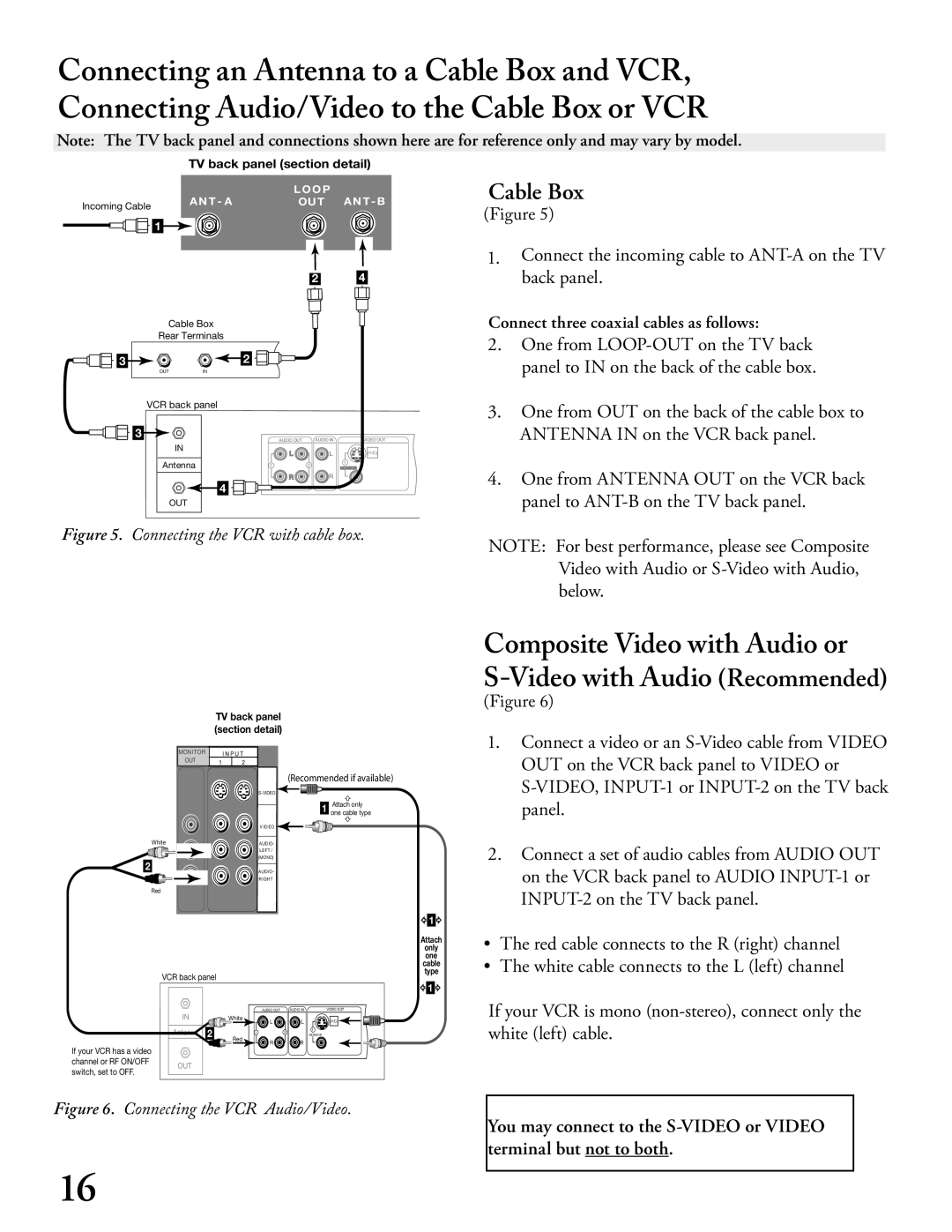
Connect the incoming cable to ANT-A on the TV back panel
Connecting an Antenna to a Cable Box or VCR
Cable Box
Antenna or Wall Outlet Cable
ANT-B on the TV back panel
One from LOOP-OUT on the TV back
Panel to ANT-B on the TV back panel
OUT on the VCR back panel to Video or
Panel
Stereo Audio System
Connecting an Audio Receiver
Receiver
DVD Player with Component Video
Connecting a DVD Player or Other S-Video Device
Other S-Video Device
DTV Connectors and Adaptors
Connecting a DTV Receiver
Component 1 and 2 may also be used for 1080i components
DTV Receiver
DTV Receiver with RGB Video Connections
Green Blue Pb/B Red Pr/R
Connecting MonitorLink
MonitorLink
† Component 2 is not available on the WT-42313
Remote Control Functions
Remote Control Functions Overview of the TV Layer Buttons
Overview
Remote Control Functions Care and Operation
Operating the Remote Control
Installing the Batteries
For Best Results from the Remote Control
Sleep Timer
Setting the Sleep Timer
Press Sleep on the remote control
Canceling the Sleep Timer
Programming the Remote Control
Use of the Remote Control with Other A/V Products
Video Products
DVD position
LD Player Audio position Receiver
Remote Control Functions Operation of PIP and POP
Remote Control Functions Special Functions
Activating the PIP and POP
Important Notes
AUDIO/VIDEO Settings Menu
Menu Screen Operations
Menu System
Choice information
Setup Menu
Main Menu Screens Overview
Captions Menu
Channel Edit Menu
Advanced Features Menu
See pages - for more detailed setup information
Chip Lock Menu
Menu
Memorize Menu
Memorize Channels
Input Assignment Menu
Clock Setting Manual
Setup Menu Manually Setting the Clock
Set Day
Setup Menu Automatically Setting the Clock
Clock Setting Auto
Time Zone
Daylight Savings Time
Language
Setup Menu Language, Front Button Lock WT-
Front Button Lock for WT-42313
Setup Menu Energy Mode WS-, WS- WS-
Energy Mode
Captions Menu Overview
Translucent gray as the background color for
Captions Menu Closed Captions, Background Color
Closed Captions
CC Background
Off No closed captions
Antenna
Channel Edit Menu Antenna, Channel Selection
Channel
Memory
Channel Edit Menu Memory, Name Selection
Name
Using The Menu Screen
Channel Edit Menu Using SQV Super Quick View
Using The Remote Control
Chip Signal Information
Chip Lock Menu Overview
Setting Up the V-CHIP Lock Passcode
Entering the Passcode
Allowing or Blocking by Ratings
Chip Hours / Lock by Time
Front Button Lock
Lock by Time
Selecting V-Chip Rating Menu
Chip Hours
Chip Start Time Chip Stop Time
Reset Color
Select to reset the PefectColor settings
Color Balance Menu
Auto Color Correction
Timer menu
Advanced Features Menu TIMER, Timer Menu, and Set Time
Set Time
Advanced Features Menu Set Day, Input, and Channel
Input
Advanced Features Menu Convergence
Convergence Menu
Convergence Screen
Advanced Convergence
Video Mute
Black Enhancement
AUDIO/VIDEO Settings Menu Overview
AUDIO/VIDEO Setting Descriptions Audio
Audio Settings
AUDIO/VIDEO Setting Descriptions Video
Video Settings
Page
Index Troubleshooting Warranty
Available On-Screen Format Sizes Operation of PIP and POP
Available On-Screen Format Sizes
Widescreen Picture 480i/480p
Operation of PIP and POP
Appendix a Bypassing Chip Lock
Bypassing the V-Chip Lock
This page intentionally blank
Input Levels When Used With Component Video Signals
Input Levels when Used With RGB Video Signals
Input when Used With DVI
Component Inputs
Receivers
Appendix C Remote Control Programming Codes
DVD Players
Satellite Receivers
VCRs
Cleaning
Appendix D Cleaning and Service
Lightly brush with a soft brush cloth, or lint brush
Follow the steps below to install and remove Diamond Shield
Installation
Cabinet Separation for Model WS-
Terminal Cover Ventilation for Model WT-
Wall
Assuring a long, trouble-free life
At Least 2 Inches Away from Wall
Index
Page
Troubleshooting Problem Possible Solution
There is a large black or gray rectangle on the screen
Page
Mitsubishi Digital Electronics America, Inc DA