Preparating your projector (continued)
Overview
1
2
3
4
5
6
7
8
9
13 12 | 11 | 10 |
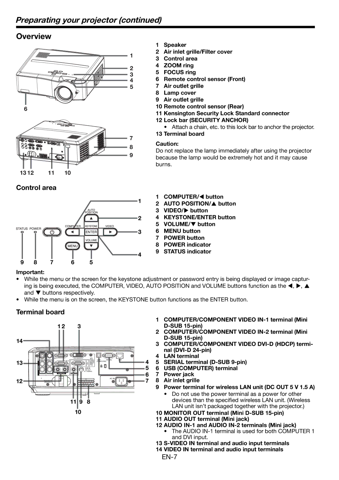
1Speaker
2Air inlet grille/Filter cover
3Control area
4ZOOM ring
5FOCUS ring
6Remote control sensor (Front)
7Air outlet grille
8Lamp cover
9Air outlet grille
10Remote control sensor (Rear)
11Kensington Security Lock Standard connector
12Lock bar (SECURITY ANCHOR)
• Attach a chain, etc. to this lock bar to anchor the projector.
13Terminal board
Caution:
Do not replace the lamp immediately after using the projector because the lamp would be extremely hot and it may cause burns.
Control area
1 | 1 | COMPUTER/W button | |
2 | AUTO POSITION/S button | ||
| |||
| 3 | VIDEO/X button | |
2 | 4 | KEYSTONE/ENTER button | |
| 5 | VOLUME/T button | |
3 | 6 | MENU button | |
| 7 | POWER button | |
| 8 | POWER indicator | |
4 | 9 | STATUS indicator | |
|
|
9 | 8 | 7 | 6 | 5 |
Important:
•While the menu or the screen for the keystone adjustment or password entry is being displayed or image captur- ing is being executed, the COMPUTER, VIDEO, AUTO POSITION and VOLUME buttons function as the W, X, S and T buttons respectively.
•While the menu is on the screen, the KEYSTONE button functions as the ENTER button.
Terminal board
14
13
12
|
|
| 1 | COMPUTER/COMPONENT VIDEO |
1 2 | 3 |
|
| |
|
|
| 2 | COMPUTER/COMPONENT VIDEO |
|
|
|
| |
|
|
| 3 | COMPUTER/COMPONENT VIDEO |
|
|
|
| nal |
|
| 4 | 4 | LAN terminal |
|
| 5 | SERIAL terminal | |
|
| 5 | 6 | USB (COMPUTER) terminal |
|
| 6 | 7 | Power jack |
|
| 7 | 8 | Air inlet grille |
|
|
| 9 | Power terminal for wireless LAN unit (DC OUT 5 V 1.5 A) |
|
|
|
| • Do not use the power terminal as a power for other |
| 11 9 | 8 |
| devices than the specified wireless LAN unit. (Wireless |
| 10 |
|
| LAN unit isn’t packaged together with the projector.) |
|
| 10 | MONITOR OUT terminal (Mini | |
|
|
| 11 | AUDIO OUT terminal (Mini jack) |
|
|
| 12 | AUDIO |
|
|
|
| • The AUDIO |
|
|
|
| and DVI input. |
|
|
| 13 | |
|
|
| 14 | VIDEO IN terminal and audio input terminals |