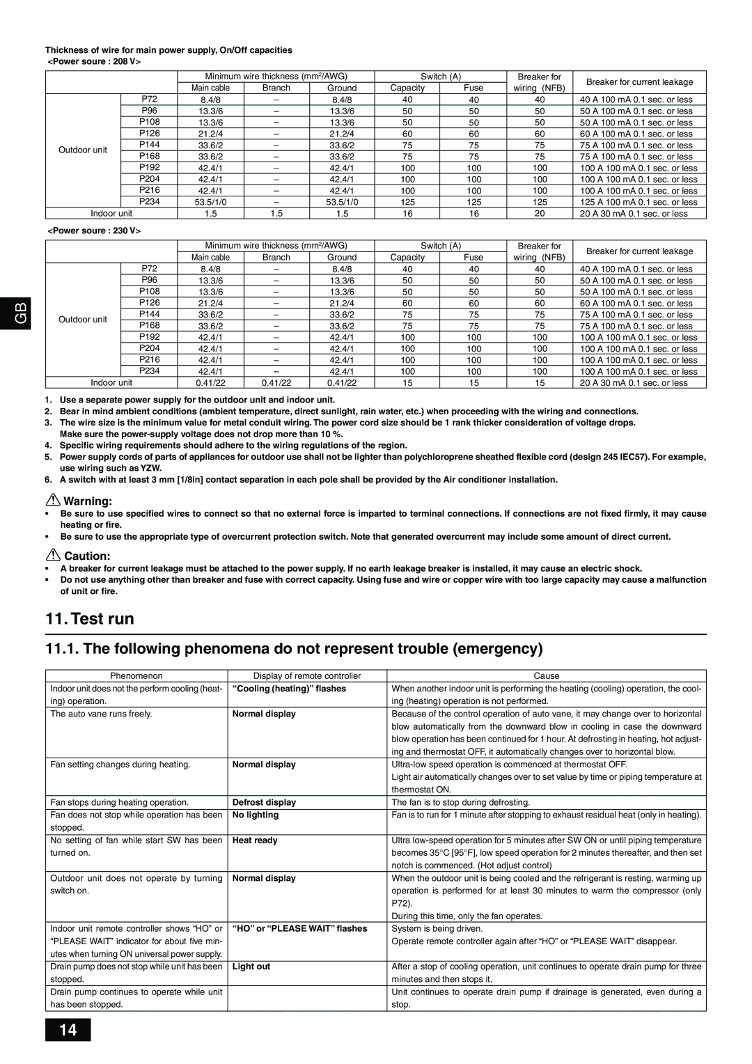
Thickness of wire for main power supply, On/Off capacities

<Power soure : 208 V>


Minimum wire thickness (mm2/AWG)

Switch (A)


Breaker for

Breaker for current leakage


Main cable

Branch

Ground

Capacity


Fuse

wiring (NFB)


P72

8.4/8

8.4/8

40


40

40

40

A 100 mA 0.1 sec. or less


P96

13.3/6

13.3/6

50


50

50

50

A 100 mA 0.1 sec. or less


P108

13.3/6

13.3/6

50


50

50

50

A 100 mA 0.1 sec. or less


P126

21.2/4

21.2/4

60


60

60

60

A 100 mA 0.1 sec. or less

Outdoor unit


P144

33.6/2

33.6/2

75


75

75

75

A 100 mA 0.1 sec. or less


P168

33.6/2

33.6/2

75


75

75

75

A 100 mA 0.1 sec. or less


P192

42.4/1

42.4/1

100


100

100

100 A 100 mA 0.1 sec. or less


P204

42.4/1

42.4/1

100


100

100

100 A 100 mA 0.1 sec. or less


P216

42.4/1

42.4/1

100


100

100

100 A 100 mA 0.1 sec. or less


P234

53.5/1/0

53.5/1/0

125


125

125

125 A 100 mA 0.1 sec. or less

Indoor unit


1.5

1.5

1.5

16


16

20

20

A 30 mA 0.1 sec. or less


<Power soure : 230 V>


Minimum wire thickness (mm2/AWG)

Switch (A)


Breaker for

Breaker for current leakage


Main cable

Branch

Ground

Capacity


Fuse

wiring (NFB)


P72

8.4/8

8.4/8

40


40

40

40

A 100 mA 0.1 sec. or less


P96

13.3/6

13.3/6

50


50

50

50

A 100 mA 0.1 sec. or less


P108

13.3/6

13.3/6

50


50

50

50

A 100 mA 0.1 sec. or less

GB


P126

21.2/4

21.2/4

60


60

60

60

A 100 mA 0.1 sec. or less


Outdoor unit


P144

33.6/2

33.6/2

75


75

75

75

A 100 mA 0.1 sec. or less


P168

33.6/2

33.6/2

75


75

75

75

A 100 mA 0.1 sec. or less


P192

42.4/1

42.4/1

100


100

100

100 A 100 mA 0.1 sec. or less


P204

42.4/1

42.4/1

100


100

100

100 A 100 mA 0.1 sec. or less


P216

42.4/1

42.4/1

100


100

100

100 A 100 mA 0.1 sec. or less


P234

42.4/1

42.4/1

100


100

100

100 A 100 mA 0.1 sec. or less


Indoor unit


0.41/22

0.41/22

0.41/22

15


15

15

20

A 30 mA 0.1 sec. or less

1.Use a separate power supply for the outdoor unit and indoor unit.

2.Bear in mind ambient conditions (ambient temperature, direct sunlight, rain water, etc.) when proceeding with the wiring and connections.

3.The wire size is the minimum value for metal conduit wiring. The power cord size should be 1 rank thicker consideration of voltage drops. Make sure the power-supply voltage does not drop more than 10 %.

4.Specific wiring requirements should adhere to the wiring regulations of the region.

5.Power supply cords of parts of appliances for outdoor use shall not be lighter than polychloroprene sheathed flexible cord (design 245 IEC57). For example, use wiring such as YZW.

6.A switch with at least 3 mm [1/8in] contact separation in each pole shall be provided by the Air conditioner installation.

Warning:

Be sure to use specified wires to connect so that no external force is imparted to terminal connections. If connections are not fixed firmly, it may cause heating or fire.

Be sure to use the appropriate type of overcurrent protection switch. Note that generated overcurrent may include some amount of direct current.

Caution:

A breaker for current leakage must be attached to the power supply. If no earth leakage breaker is installed, it may cause an electric shock.

Do not use anything other than breaker and fuse with correct capacity. Using fuse and wire or copper wire with too large capacity may cause a malfunction of unit or fire.

11. Test run

11.1. The following phenomena do not represent trouble (emergency)

Phenomenon

Display of remote controller

Cause

Indoor unit does not the perform cooling (heat-

“Cooling (heating)” flashes

When another indoor unit is performing the heating (cooling) operation, the cool-

ing) operation.


ing (heating) operation is not performed.

The auto vane runs freely.

Normal display

Because of the control operation of auto vane, it may change over to horizontal


blow automatically from the downward blow in cooling in case the downward


blow operation has been continued for 1 hour. At defrosting in heating, hot adjust-


ing and thermostat OFF, it automatically changes over to horizontal blow.

Fan setting changes during heating.

Normal display

Ultra-low speed operation is commenced at thermostat OFF.


Light air automatically changes over to set value by time or piping temperature at


thermostat ON.

Fan stops during heating operation.

Defrost display

The fan is to stop during defrosting.


Fan does not stop while operation has been

No lighting

Fan is to run for 1 minute after stopping to exhaust residual heat (only in heating).

stopped.


No setting of fan while start SW has been

Heat ready

Ultra low-speed operation for 5 minutes after SW ON or until piping temperature

turned on.


becomes 35°C [95°F], low speed operation for 2 minutes thereafter, and then set


notch is commenced. (Hot adjust control)

Outdoor unit does not operate by turning

Normal display

When the outdoor unit is being cooled and the refrigerant is resting, warming up

switch on.


operation is performed for at least 30 minutes to warm the compressor (only


P72).


During this time, only the fan operates.

Indoor unit remote controller shows “HO” or

“HO” or “PLEASE WAIT” flashes

System is being driven.

“PLEASE WAIT” indicator for about five min-


Operate remote controller again after “HO” or “PLEASE WAIT” disappear.

utes when turning ON universal power supply.


Drain pump does not stop while unit has been

Light out

After a stop of cooling operation, unit continues to operate drain pump for three

stopped.


minutes and then stops it.

Drain pump continues to operate while unit


Unit continues to operate drain pump if drainage is generated, even during a

has been stopped.


stop.


14

Page 14
Image 14
Mitsumi electronic PUHY-P-TGMU-A installation manual Test run, Following phenomena do not represent trouble emergency

PUHY-P-TGMU-A specifications

The Mitsumi Electronic PUHY-P-TGMU-A is a cutting-edge multi-split air conditioning system that adopts advanced technologies to enhance indoor comfort and energy efficiency. Designed for both residential and commercial use, this unit stands out due to its innovative features and remarkable performance capabilities.

One of the key characteristics of the PUHY-P-TGMU-A is its ability to effectively cool or heat multiple spaces simultaneously. With a capacity range that meets the demands of diverse environments, this system can seamlessly cater to larger installations. This makes it ideal for office buildings, retail spaces, or homes with multiple rooms requiring climate control.

The unit is equipped with inverter technology, which allows for variable speed operation of the compressor. This not only results in significant energy savings but also provides a stable temperature and optimal comfort levels. The inverter technology adjusts the power consumption based on the cooling or heating requirements in real-time, thereby reducing energy costs and increasing overall efficiency.

Another outstanding feature is the advanced air filtration system. The PUHY-P-TGMU-A incorporates a combination of pre-filters and HEPA filters that effectively reduce airborne particles, allergens, and pollutants. This ensures that the air circulated within the environment remains clean and healthy, making it an excellent choice for those with respiratory sensitivities.

In addition, the unit comes with smart connectivity options. Users can control the system remotely through a smartphone app, allowing for seamless adjustments to settings from anywhere at any time. This smart technology not only enhances convenience but also enables users to monitor energy consumption and adjust schedules to maximize efficiency when spaces are unoccupied.

Thermal management technologies integrated into the PUHY-P-TGMU-A ensure rapid and effective heat exchange, further improving performance. Its sleek design and compact dimensions allow for flexible installation, making it suitable for a variety of architectural styles.

The PUHY-P-TGMU-A is not only about performance; it emphasizes quiet operation too. The design minimizes noise levels, ensuring that the atmosphere remains tranquil even during peak operation.

In summary, the Mitsumi Electronic PUHY-P-TGMU-A combines sophisticated technology, energy efficiency, and user-friendly features to create a versatile and highly effective climate control solution. Whether for personal or business use, this multi-split air conditioning system proves to be an investment in comfort and innovation.