Chapter 1 | Overview |
|
|
The mo8 Enclosure
The mo8 enclosure can be used in a number of different configurations depending on the needs of the end user. Units are shipped with rack ears, which can be front or rear mounted or can rotate for vertical or horizontal surface mounting. Optional rubber stage boots allow the units to be used as stage boxes.
An optional contractor panel can be ordered, which then allows the end user to terminate all analog connections with simple “phoenix” screw terminal connectors or utilize a standard DB25 “break out cable” instead of the front panel XLR connectors. This also allows passive “splitting” of the analog signals if needed. Pro Co offers whatever breakout cables you need. Just ask for them when you order your system.
mo8 Front View with Rack Ears | mo8 Front View with optional Stage Boots |
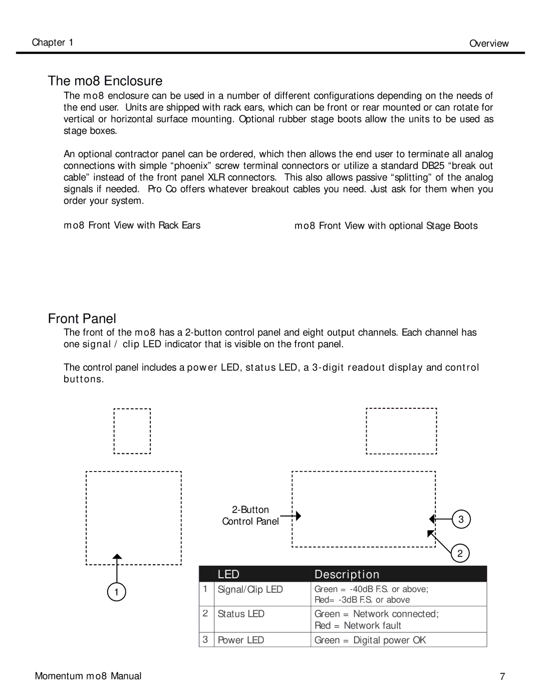
Front Panel
The front of the mo8 has a
The control panel includes a power LED, status LED, a
|
|
|
| 3 | ||||||
|
|
|
| Control Panel |
|
| ||||
|
|
|
|
|
|
|
| 2 | ||
|
|
|
|
|
|
|
|
|
|
|
|
|
|
|
|
|
|
|
|
|
|
|
|
|
| LED |
|
|
| Description | ||
|
|
| Signal/Clip LED |
|
|
| ||||
|
| 1 | Green = | |||||||
1 | ||||||||||
|
|
|
|
|
|
|
| Red= | ||
|
| 2 | Status LED | Green = Network connected; | ||||||
|
|
|
|
|
|
|
| Red = Network fault | ||
|
|
|
|
|
|
|
|
|
|
|
|
| 3 | Power LED | Green = Digital power OK | ||||||
|
|
|
|
|
|
|
|
|
|
|
Momentum mo8 Manual | 7 |