Motorola DCT6200, DCT5100 SafetyandInstallTips, YourHDDigitalReceiverBackPanel, Safety First

Models: DCT6200 DCT5100

1 8
Download 8 pages 34.82 Kb
Page 3
Image 3
SafetyandInstallTips

Safety FirstUseful Install TipsYourHDDigitalReceiverBackPanelManual backgroundSafetyManual backgroundManual backgroundManual backgroundandManual backgroundManual backgroundManual backgroundInstallManual backgroundManual backgroundTipsManual backgroundManual backgroundManual backgroundManual backgroundManual backgroundManual backgroundManual backgroundManual backgroundManual backgroundManual backgroundManual backgroundManual backgroundManual background

Safety First

Do not plug the high-definition digital receiver into an electrical outlet until after you have connected it to the TV, the cable wall outlet and any other devices.

Position the high-definition digital receiver with at least 2 inches of space on all sides to allow the device to properly cool when operating.

Ensure that the high-definition digital receiver is not near an external heat source that could raise the temperature of the unit.

Do not expose the high-definition digital receiver to moisture. Unplug the receiver before cleaning and avoid using liquid or aerosol cleaners.

Use a surge protector.

Useful Install Tips

Connect the high-definition digital video receiver directly to the cable wall outlet.

Be sure that all connections between the TV, VCR, digital receiver and the cable wall outlet are secure.

There are two different cable options that can be used to deliver HD video signal to your HDTV. This kit includes standard component cables which are one of the most common connection options. DVI cables are optional and sold separately.

a. Component Input Cables

High-quality video connection that uses three separate component cables, generally color-coded green, blue and red. These are also called Y, Pb, Pr Cables.

b. DVI Connectors

Digital Video Interface cables are all digital, high-quality video connectors that are more common on newer high- definition televisions.

• See http://charter.com/quickstart for additional wiring configurations.

Manual backgroundManual backgroundManual backgroundManual backgroundYourManual backgroundManual backgroundHDManual backgroundManual backgroundDigitalManual backgroundManual backgroundReceiverManual backgroundManual backgroundBackManual backgroundManual backgroundPanelManual background

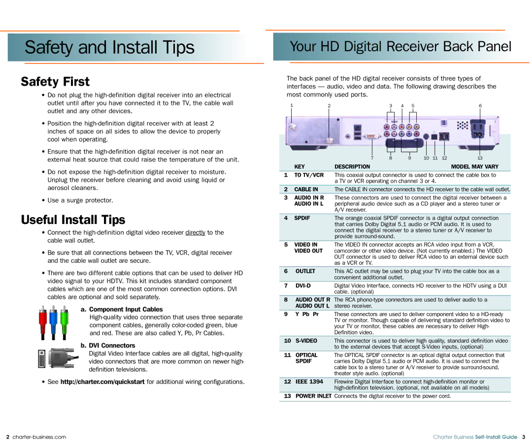
The back panel of the HD digital receiver consists of three types of interfaces — audio, video and data. The following drawing describes the most commonly used ports.

1

2


3

4

5

6


7

8

9

10

11

12

13

KEY

DESCRIPTION


MODEL MAY VARY

1TO TV/VCR This coaxial output connector is used to connect the cable box to a TV or VCR operating on channel 3 or 4.

2CABLE IN The CABLE IN connector connects the HD receiver to the cable wall outlet.

3AUDIO IN R These connectors are used to connect the digital receiver between a AUDIO IN L peripheral audio device such as a CD player and a stereo tuner or

A/V receiver.

4 SPDIF

The orange coaxial SPDIF connector is a digital output connection


that carries Dolby Digital 5.1 audio or PCM audio. It is used to


connect the digital receiver to a stereo tuner or A/V receiver to


provide surround-sound.

5VIDEO IN The VIDEO IN connector accepts an RCA video input from a VCR, VIDEO OUT camcorder or other video device. (Not currently enabled.) The VIDEO

OUT connector is used to deliver RCA video to an external device such as a VCR or TV.

6OUTLET This AC outlet may be used to plug your TV into the cable box as a convenient additional outlet.

7 DVI-D

Digital Video Interface, connects HD receiver to the HDTV using a DUI


cable. (optional)

8AUDIO OUT R The RCA phono-type connectors are used to deliver audio to a AUDIO OUT L stereo receiver.

9Y Pb Pr These connectors are used to deliver component video to a HD-ready TV or monitor. Though capable of delivering standard definition video to your TV or monitor, these cables are necessary to deliver High- Definition video.

10S-VIDEO This connector is used to deliver high quality, standard definition video to the external devices that accept S-Video inputs, (optional)

11OPTICAL The OPTICAL SPDIF connector is an optical digital output connection that

SPDIF

carries Dolby Digital 5.1 audio or PCM audio. It is used to connect the


cable box to a stereo tuner or A/V receiver to provide surround-sound,


theater style audio. (optional)

12IEEE 1394 Firewire Digital Interface to connect high-definition monitor or high-definition television. (optional, not available on all models)

13POWER INLET Connects the digital receiver to the power cord.

2 charter-business.com

Charter Business Self-Install Guide 3

Page 3
Image 3
Motorola DCT6200, DCT5100 SafetyandInstallTips, YourHDDigitalReceiverBackPanel, Safety First, Useful Install Tips