Motorola DCT5100, DCT6200 quick start InstallationDiagrams, Installation Diagrams, Hdtv

Models: DCT6200 DCT5100

1 8
Download 8 pages 34.82 Kb
Page 4
Image 4
InstallationDiagrams
(DVI cable sold separately)

Installation DiagramsHDTVManual backgroundManual backgroundInstallationManual backgroundManual backgroundManual backgroundDiagramsManual backgroundManual backgroundManual backgroundManual backgroundManual backgroundManual backgroundManual backgroundManual backgroundManual backgroundManual backgroundManual backgroundManual backgroundManual backgroundManual backgroundManual backgroundManual background

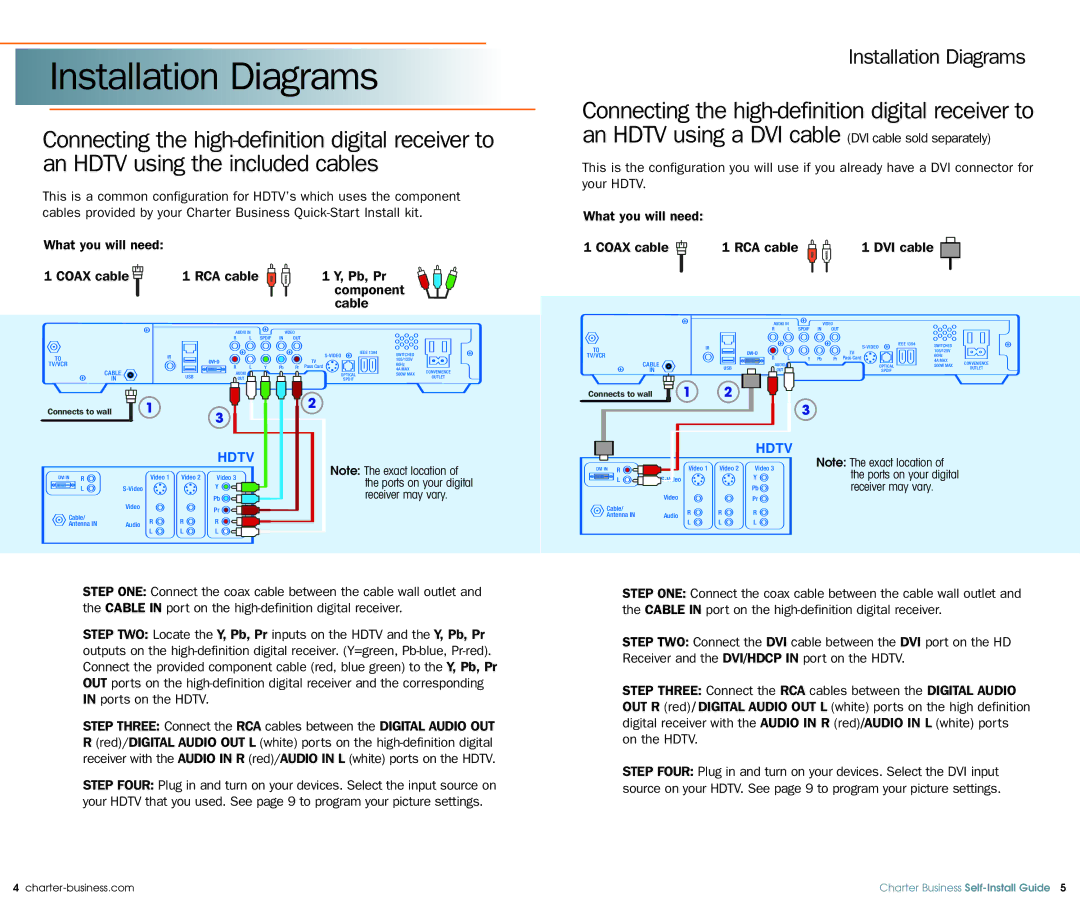
Connecting the high-definition digital receiver to an HDTV using the included cables

Installation Diagrams

Connecting the high-definition digital receiver to an HDTV using a DVI cable

This is the configuration you will use if you already have a DVI connector for your HDTV.

This is a common configuration for HDTV’s which uses the component cables provided by your Charter Business Quick-Start Install kit.

What you will need:

1 COAX cable


1 RCA cable


1 Y, Pb, Pr


component


cable

What you will need:


1 COAX cable

1 RCA cable

1 DVI cable


AUDIO IN


VIDEO


AUDIO IN


VIDEO


R

L

SPDIF

IN

OUT


R

L

SPDIF

IN

OUT


IEEE 1394

SWITCHED


TO


IR


S-VIDEO


105/125V


IEEE 1394


TV


IR


S-VIDEO

SWITCHED


TV/VCR


60Hz

TO


TV


105/125V


CABLE


R

L

Y

Pb

Pr


4A MAX

TV/VCR


R

L

Y

Pb

Pr

Pass Card


60Hz


USB


AUDIO


OPTICAL

500W MAX


CABLE


4A MAX

CONVENIENCE


IN


OUT


SPDIF


AUDIO


OPTICAL


USB


500W MAX

OUTLET


IN


OUT


SPDIF


1


2


Connects to wall


1

2


Connects to wall


3


3


HDTV


HDTV


Note: The exact location of


Note: The exact location of


Video 1

Video 2

Video 3


Video 1

Video 2


DVI IN

R


the ports on your digital

DVI IN

R


Video 3


L


S-Video


Y


Y


the ports on your digital


receiver may vary.


L

S-Video


Pb


Pb


receiver may vary.


Video


Pr


Video


Pr


Cable/


R

R

R


Cable/


Antenna IN


Audio


R

R

R


L

L

L


Antenna IN

Audio


L

L

L


CONVENIENCE

OUTLET

STEP ONE: Connect the coax cable between the cable wall outlet and the CABLE IN port on the high-definition digital receiver.

STEP TWO: Locate the Y, Pb, Pr inputs on the HDTV and the Y, Pb, Pr outputs on the high-definition digital receiver. (Y=green, Pb-blue, Pr-red). Connect the provided component cable (red, blue green) to the Y, Pb, Pr OUT ports on the high-definition digital receiver and the corresponding IN ports on the HDTV.

STEP THREE: Connect the RCA cables between the DIGITAL AUDIO OUT R (red)/DIGITAL AUDIO OUT L (white) ports on the high-definition digital receiver with the AUDIO IN R (red)/AUDIO IN L (white) ports on the HDTV.

STEP FOUR: Plug in and turn on your devices. Select the input source on your HDTV that you used. See page 9 to program your picture settings.

STEP ONE: Connect the coax cable between the cable wall outlet and the CABLE IN port on the high-definition digital receiver.

STEP TWO: Connect the DVI cable between the DVI port on the HD Receiver and the DVI/HDCP IN port on the HDTV.

STEP THREE: Connect the RCA cables between the DIGITAL AUDIO OUT R (red) / DIGITAL AUDIO OUT L (white) ports on the high definition digital receiver with the AUDIO IN R (red)/AUDIO IN L (white) ports on the HDTV.

STEP FOUR: Plug in and turn on your devices. Select the DVI input source on your HDTV. See page 9 to program your picture settings.

4 charter-business.com

Charter Business Self-Install Guide 5

Page 4
Image 4
Motorola DCT5100, DCT6200 quick start InstallationDiagrams, Installation Diagrams, Hdtv