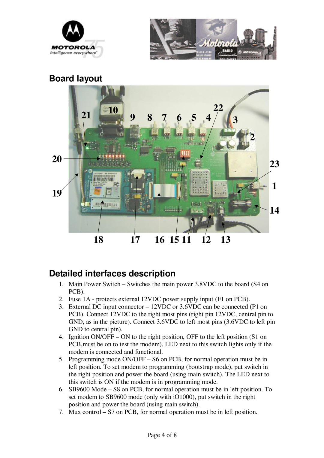
Board layout
21 | 10 | 9 | 8 | 7 | 6 | 5 | 4 | 22 |
| 3 |
2
20
19
23
 1
1
![]() 14
14
18 | 17 | 16 15 11 | 12 | 13 |
Detailed interfaces description
1.Main Power Switch – Switches the main power 3.8VDC to the board (S4 on PCB).
2.Fuse 1A - protects external 12VDC power supply input (F1 on PCB).
3.External DC input connector – 12VDC or 3.6VDC can be connected (P1 on PCB). Connect 12VDC to the right most pins (right pin 12VDC, central pin to GND, as in the picture). Connect 3.6VDC to left most pins (3.6VDC to left pin GND to central pin).
4.Ignition ON/OFF – ON to the right position, OFF to the left position (S1 on PCB,must be on to test the modem). LED next to this switch lights only if the modem is connected and functional.
5.Programming mode ON/OFF – S6 on PCB, for normal operation must be in left position. To set modem to programming (bootstrap mode), put switch in the right position and power the board (using main switch). The LED next to this switch is ON if the modem is in programming mode.
6.SB9600 Mode – S8 on PCB, for normal operation must be in left position. To set modem to SB9600 mode (only with iO1000), put switch in the right position and power the board (using main switch).
7.Mux control – S7 on PCB, for normal operation must be in left position.
Page 4 of 8