Block Diagram
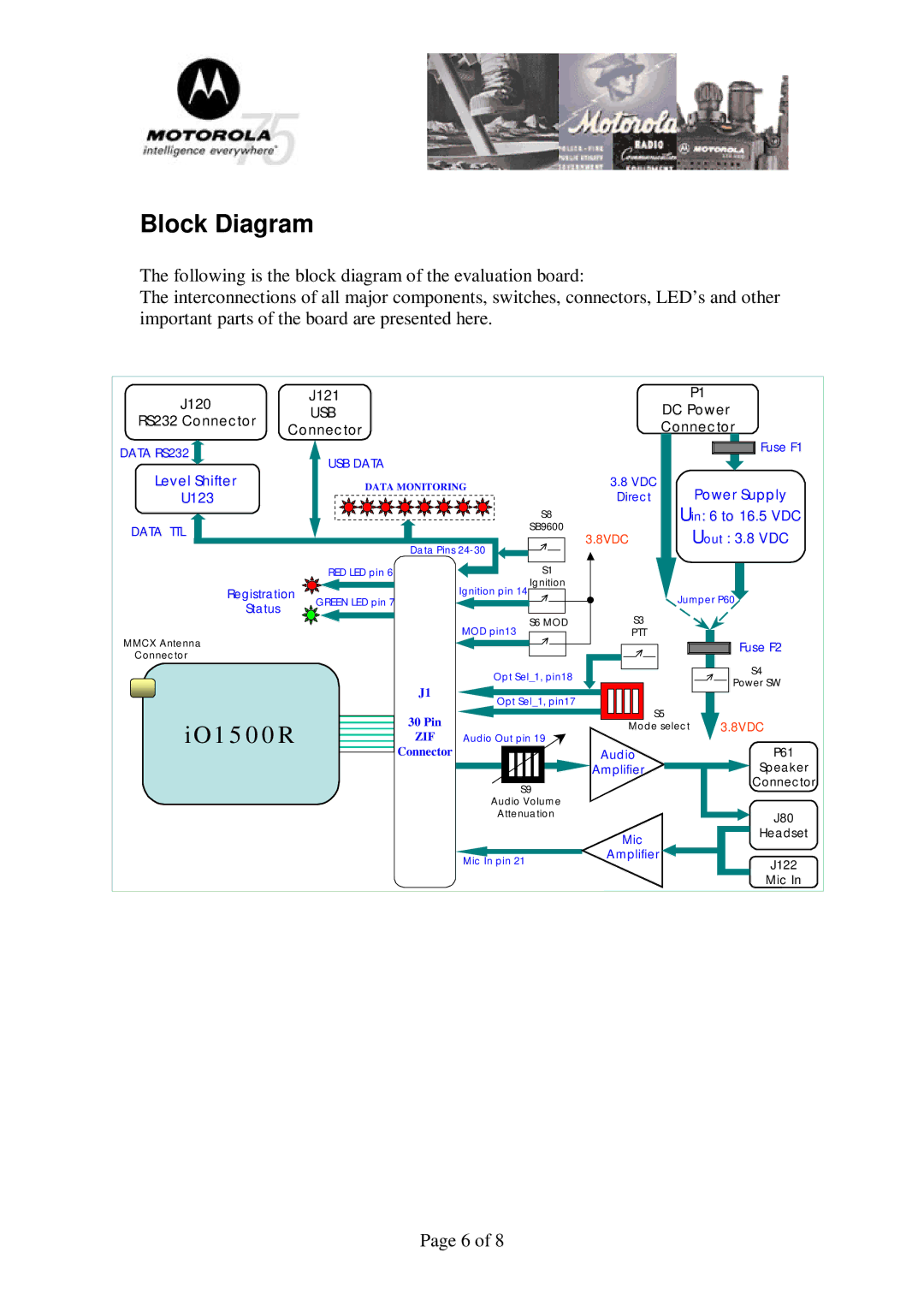
The following is the block diagram of the evaluation board:
The interconnections of all major components, switches, connectors, LED’s and other important parts of the board are presented here.
J120 |
| J121 |
|
|
| P1 |
| USB |
|
| DC Power | ||
RS232 Connector |
|
|
| |||
Connector |
|
| Connector | |||
|
|
| ||||
DATA RS232 |
| USB DATA |
|
|
| Fuse F1 |
|
|
|
|
| ||
Level Shifter |
|
|
|
|
| |
| DATA MONITORING |
| 3.8 VDC | Power Supply | ||
U123 |
|
|
|
| Direct | |
|
|
|
| S8 | Uin: 6 to 16.5 VDC | |
DATA TTL |
|
|
| SB9600 | 3.8VDC | Uout : 3.8 VDC |
|
| Data Pins |
| |||
|
|
|
|
| ||
|
| RED LED pin 6 |
| S1 |
|
|
Registration | GREEN LED pin 7 | Ignition pin 14 Ignition | Jumper P60 | |||
Status |
|
|
| |||
|
|
| S6 MOD | S3 |
| |
|
|
| MOD pin13 |
| ||
MMCX Antenna |
|
|
| PTT | Fuse F2 | |
|
|
|
|
| ||
Connector |
|
|
|
|
|
|
|
|
| Opt Sel_1, pin18 |
| S4 | |
|
|
|
| Power SW | ||
|
| J1 |
|
|
| |
|
| Opt Sel_1, pin17 |
|
| ||
|
|
| S5 |
| ||
iO1500R | 30 Pin |
|
| 3.8VDC | ||
|
| Mode select | ||||
ZIF | Audio Out pin 19 |
| P61 | |||
|
| Connector |
|
| Audio | |
|
|
|
|
| Amplifier | Speaker |
|
|
|
| S9 |
| Connector |
|
|
| Audio Volume |
|
| |
|
|
| Attenuation |
| J80 | |
|
|
|
|
| Mic | Headset |
|
|
|
|
|
| |
|
|
| Mic In pin 21 | Amplifier | J122 | |
|
|
|
| |||
|
|
|
|
|
| Mic In |
Page 6 of 8