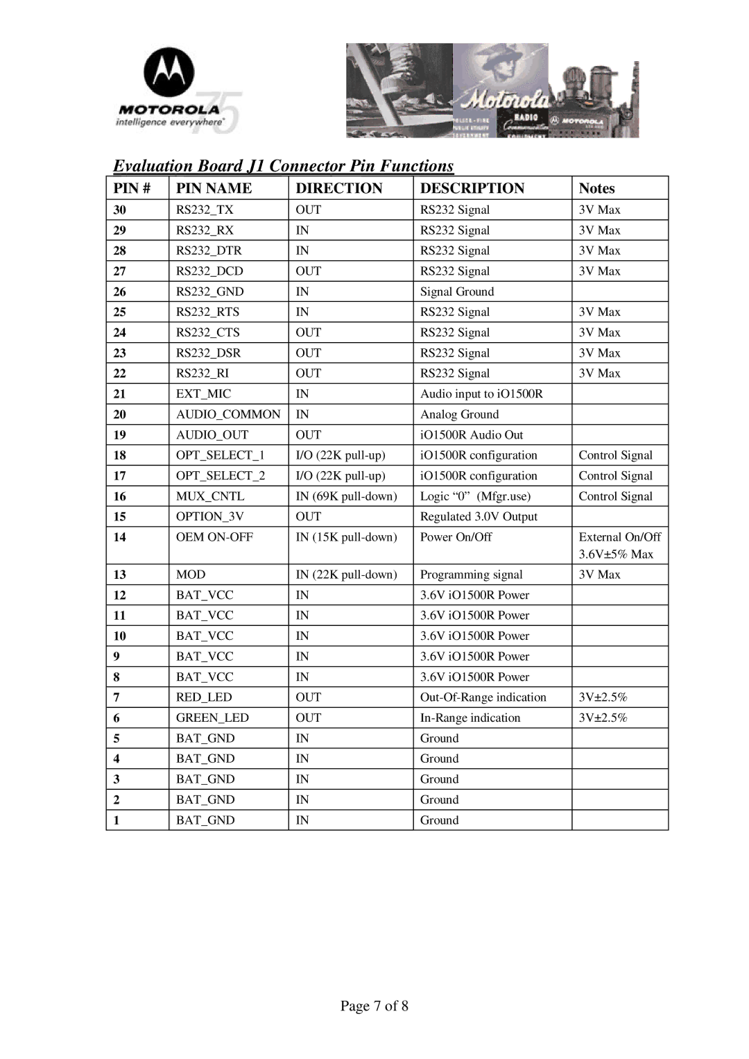
Evaluation Board J1 Connector Pin Functions
PIN # | PIN NAME | DIRECTION | DESCRIPTION | Notes |
30 | RS232_TX | OUT | RS232 Signal | 3V Max |
|
|
|
|
|
29 | RS232_RX | IN | RS232 Signal | 3V Max |
28 | RS232_DTR | IN | RS232 Signal | 3V Max |
|
|
|
|
|
27 | RS232_DCD | OUT | RS232 Signal | 3V Max |
|
|
|
|
|
26 | RS232_GND | IN | Signal Ground |
|
25 | RS232_RTS | IN | RS232 Signal | 3V Max |
|
|
|
|
|
24 | RS232_CTS | OUT | RS232 Signal | 3V Max |
|
|
|
|
|
23 | RS232_DSR | OUT | RS232 Signal | 3V Max |
22 | RS232_RI | OUT | RS232 Signal | 3V Max |
|
|
|
|
|
21 | EXT_MIC | IN | Audio input to iO1500R |
|
|
|
|
|
|
20 | AUDIO_COMMON | IN | Analog Ground |
|
|
|
|
|
|
19 | AUDIO_OUT | OUT | iO1500R Audio Out |
|
18 | OPT_SELECT_1 | I/O (22K | iO1500R configuration | Control Signal |
|
|
|
|
|
17 | OPT_SELECT_2 | I/O (22K | iO1500R configuration | Control Signal |
|
|
|
|
|
16 | MUX_CNTL | IN (69K | Logic “0” (Mfgr.use) | Control Signal |
15 | OPTION_3V | OUT | Regulated 3.0V Output |
|
|
|
|
|
|
14 | OEM | IN (15K | Power On/Off | External On/Off |
|
|
|
| 3.6V±5% Max |
|
|
|
|
|
13 | MOD | IN (22K | Programming signal | 3V Max |
12 | BAT_VCC | IN | 3.6V iO1500R Power |
|
|
|
|
|
|
11 | BAT_VCC | IN | 3.6V iO1500R Power |
|
10 | BAT_VCC | IN | 3.6V iO1500R Power |
|
|
|
|
|
|
9 | BAT_VCC | IN | 3.6V iO1500R Power |
|
|
|
|
|
|
8 | BAT_VCC | IN | 3.6V iO1500R Power |
|
7 | RED_LED | OUT | 3V±2.5% | |
|
|
|
|
|
6 | GREEN_LED | OUT | 3V±2.5% | |
|
|
|
|
|
5 | BAT_GND | IN | Ground |
|
4 | BAT_GND | IN | Ground |
|
|
|
|
|
|
3 | BAT_GND | IN | Ground |
|
|
|
|
|
|
2 | BAT_GND | IN | Ground |
|
|
|
|
|
|
1 | BAT_GND | IN | Ground |
|
Page 7 of 8
