Freescale Semiconductor, Inc.
Hardware Description and Board Operation
When
their own application program. For more details on flash memory programming, please refer to Appendix C .ARCHIVED BY FREESCALE SEMICONDUCTOR, INC. 2005
Semiconductor, Inc.
SEMICONDUCTOR, INC. 2005
3.6.3 EMU ROM
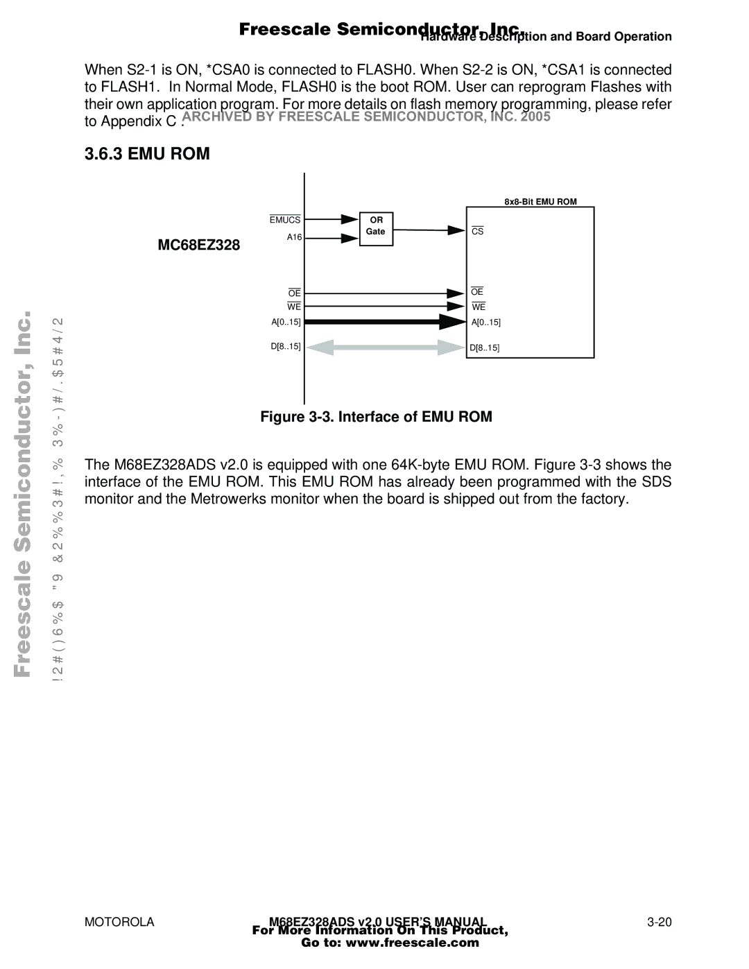
MC68EZ328
|
| |
EMUCS | OR |
|
A16 | Gate | CS |
|
| |
OE |
| OE |
WE |
| WE |
A[0..15] |
| A[0..15] |
D[8..15] |
| D[8..15] |
Figure 3-3. Interface of EMU ROM
Freescale
ARCHIVED BY FREESCALE
The M68EZ328ADS v2.0 is equipped with one
MOTOROLAM68EZ328ADS v2.0 USER’S MANUAL3-20
For More Information On This Product,
Go to: www.freescale.com