Freescale Semiconductor, Inc.
ARCHIVED BY FREESCALE SEMICONDUCTOR, INC. 2005
Freescale Semiconductor, Inc.
Hardware Description and Board Operation
3.4 OPERATION MODES
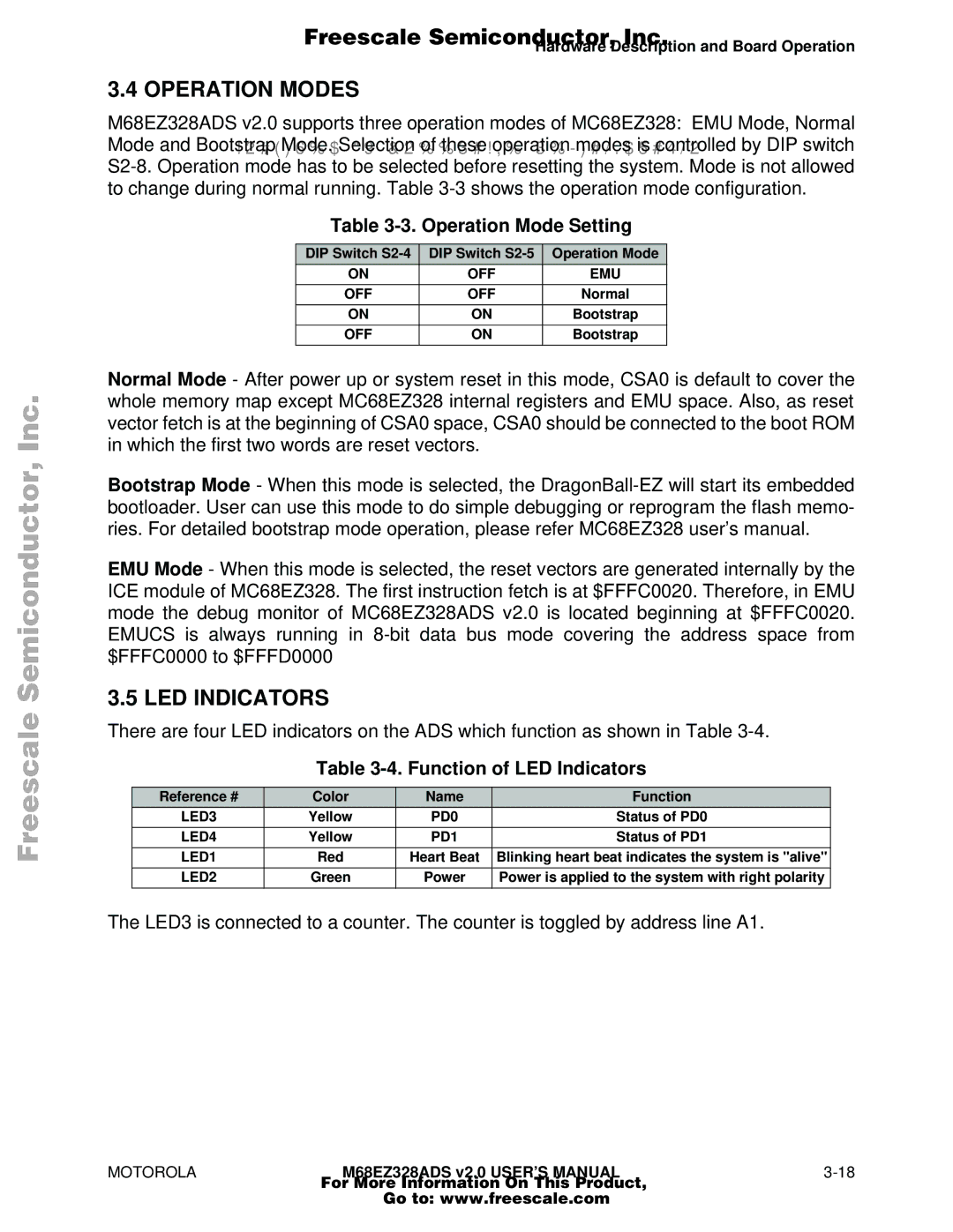
M68EZ328ADS v2.0 supports three operation modes of MC68EZ328: EMU Mode, Normal
Mode and BootstrapARCHIVEDModeBY. SelectionFREESCALEof theseSEMICONDUCTOR,operation modesINCis .controlled2005 by DIP switch
Table 3-3. Operation Mode Setting
DIP Switch | DIP Switch | Operation Mode |
ON | OFF | EMU |
|
|
|
OFF | OFF | Normal |
|
|
|
ON | ON | Bootstrap |
|
|
|
OFF | ON | Bootstrap |
|
|
|
Normal Mode - After power up or system reset in this mode, CSA0 is default to cover the whole memory map except MC68EZ328 internal registers and EMU space. Also, as reset vector fetch is at the beginning of CSA0 space, CSA0 should be connected to the boot ROM in which the first two words are reset vectors.
Bootstrap Mode - When this mode is selected, the
EMU Mode - When this mode is selected, the reset vectors are generated internally by the ICE module of MC68EZ328. The first instruction fetch is at $FFFC0020. Therefore, in EMU mode the debug monitor of MC68EZ328ADS v2.0 is located beginning at $FFFC0020. EMUCS is always running in
3.5 LED INDICATORS
There are four LED indicators on the ADS which function as shown in Table
Table 3-4. Function of LED Indicators
Reference # | Color | Name | Function |
LED3 | Yellow | PD0 | Status of PD0 |
|
|
|
|
LED4 | Yellow | PD1 | Status of PD1 |
|
|
|
|
LED1 | Red | Heart Beat | Blinking heart beat indicates the system is "alive" |
|
|
|
|
LED2 | Green | Power | Power is applied to the system with right polarity |
|
|
|
|
The LED3 is connected to a counter. The counter is toggled by address line A1.
MOTOROLAM68EZ328ADS v2.0 USER’S MANUAL3-18
For More Information On This Product,
Go to: www.freescale.com
