QIP6200/64xx – Front and Back Panels
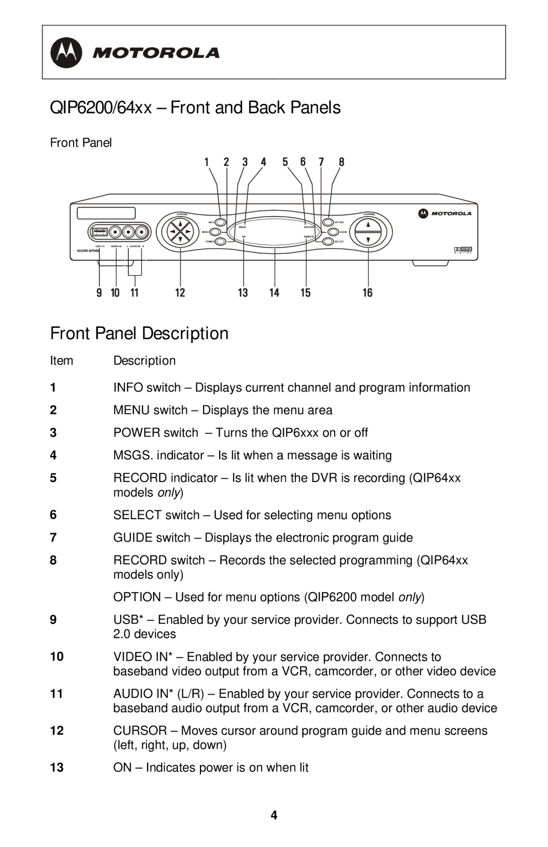
Front Panel
Front Panel Description
Item Description
1INFO switch – Displays current channel and program information
2MENU switch – Displays the menu area
3POWER switch – Turns the QIP6xxx on or off
4MSGS. indicator – Is lit when a message is waiting
5RECORD indicator – Is lit when the DVR is recording (QIP64xx models only)
6SELECT switch – Used for selecting menu options
7GUIDE switch – Displays the electronic program guide
8RECORD switch – Records the selected programming (QIP64xx models only)
OPTION – Used for menu options (QIP6200 model only)
9USB* – Enabled by your service provider. Connects to support USB 2.0 devices
10VIDEO IN* – Enabled by your service provider. Connects to baseband video output from a VCR, camcorder, or other video device
11AUDIO IN* (L/R) – Enabled by your service provider. Connects to a baseband audio output from a VCR, camcorder, or other audio device
12CURSOR – Moves cursor around program guide and menu screens (left, right, up, down)
13ON – Indicates power is on when lit
4