Chapter 1 – Product Description and Specifications
RF Specifications
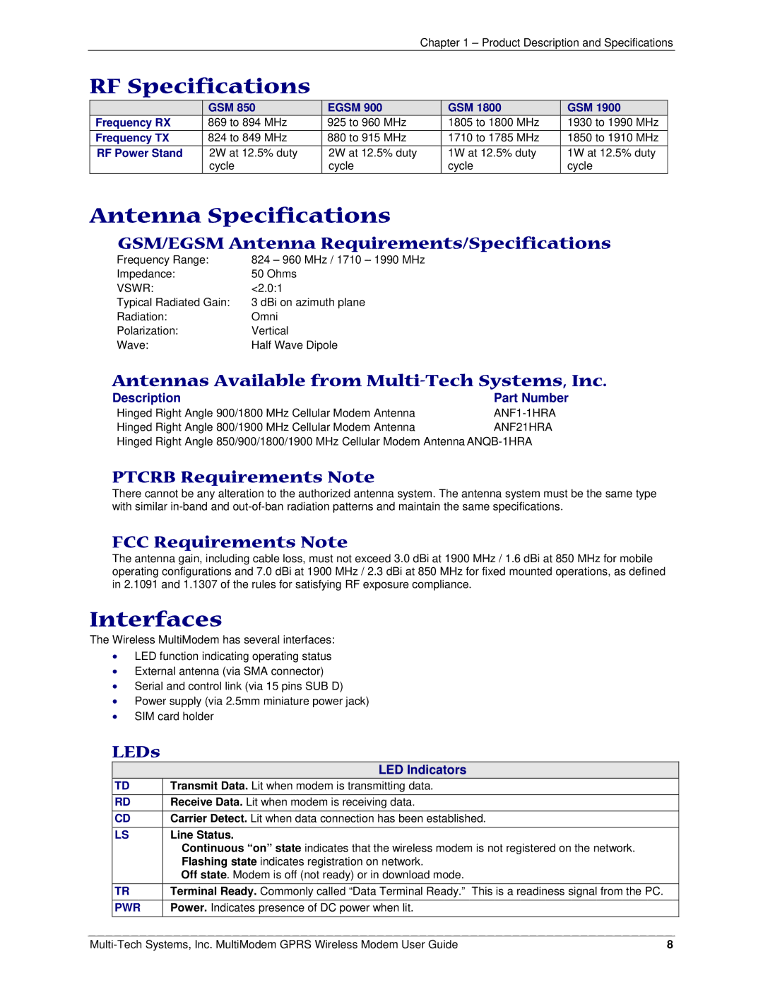
| GSM 850 | EGSM 900 |
Frequency RX | 869 to 894 MHz | 925 to 960 MHz |
Frequency TX | 824 to 849 MHz | 880 to 915 MHz |
RF Power Stand | 2W at 12.5% duty | 2W at 12.5% duty |
| cycle | cycle |
GSM 1800
1805 to 1800 MHz
1710 to 1785 MHz
1W at 12.5% duty cycle
GSM 1900
1930 to 1990 MHz
1850 to 1910 MHz
1W at 12.5% duty cycle
Antenna Specifications
GSM/EGSM Antenna Requirements/Specifications
Frequency Range: | 824 – 960 MHz / 1710 – 1990 MHz |
Impedance: | 50 Ohms |
VSWR: | <2.0:1 |
Typical Radiated Gain: | 3 dBi on azimuth plane |
Radiation: | Omni |
Polarization: | Vertical |
Wave: | Half Wave Dipole |
Antennas Available from Multi-Tech Systems, Inc.
Description | Part Number |
Hinged Right Angle 900/1800 MHz Cellular Modem Antenna | |
Hinged Right Angle 800/1900 MHz Cellular Modem Antenna | ANF21HRA |
Hinged Right Angle 850/900/1800/1900 MHz Cellular Modem Antenna
PTCRB Requirements Note
There cannot be any alteration to the authorized antenna system. The antenna system must be the same type with similar
FCC Requirements Note
The antenna gain, including cable loss, must not exceed 3.0 dBi at 1900 MHz / 1.6 dBi at 850 MHz for mobile operating configurations and 7.0 dBi at 1900 MHz / 2.3 dBi at 850 MHz for fixed mounted operations, as defined in 2.1091 and 1.1307 of the rules for satisfying RF exposure compliance.
Interfaces
The Wireless MultiModem has several interfaces:
•LED function indicating operating status
•External antenna (via SMA connector)
•Serial and control link (via 15 pins SUB D)
•Power supply (via 2.5mm miniature power jack)
•SIM card holder
LEDs
| LED Indicators |
TD | Transmit Data. Lit when modem is transmitting data. |
RD | Receive Data. Lit when modem is receiving data. |
CD | Carrier Detect. Lit when data connection has been established. |
LS | Line Status. |
| Continuous “on” state indicates that the wireless modem is not registered on the network. |
| Flashing state indicates registration on network. |
| Off state. Modem is off (not ready) or in download mode. |
TR | Terminal Ready. Commonly called “Data Terminal Ready.” This is a readiness signal from the PC. |
PWR | Power. Indicates presence of DC power when lit. |
8 |