HPLA/HPHA-SERIES
HPLA/HPHA-SERIES 36TROWEL- Proposition 65WARNING
Page
HPLA/HPHA-SERIES 36TROWEL-TABLE of Contents
Order via Fax Dealers Only
HPLA/HPHA-SERIES 36TROWEL- Parts Ordering Procedures
Best Deal! Order via Internet Dealers Only
HPLA/HPHA-SERIES 36TROWEL-TRAINING Checklist
Training Checklist
Read Operator’s Manual completely
Machine layout, location of components, checking of engine
HPLA/HPHA-SERIES 36TROWEL- Daily PRE-OPERATION Checklist
Daily PRE-OPERATION Checklist
HPLA/HPHA-SERIES 36 TROWEL- Safety Message Alert Symbols
Do not follow directions
You do not follow instructions
Always wear approved eye and hearing protection
Property, or the surrounding
Safety
HPLA/HPHA-SERIES 36TROWEL- Rules for Safe Operation
Maintenance Safety
HPLA/HPHA-SERIES 36TROWEL- Rules for Safe Operation
Emergencies
Always know the location of the nearest and first aid kit
HPLA/HPHA-SERIES 36TROWEL- Operation and Safety Decals
Machine Safety Decals
SideView
HPLA/HPHA-SERIES 36TROWEL- Specifications Trowel
Height Lifting Hook 36.7 in 931.6 mm
HPLA/HPHA-SERIES 36TROWEL- Specifications Engine
HPLA/HPHA-SERIES 36TROWEL- General Information
HPLA/HPHA-SERIES 36TROWEL- Controls and Components
HPLA/HPHA-SERIES 36 Walk- Behind Trowels
HPLA/HPHA-SERIES 36TROWEL- Controls and Components
HPLA/HPHA-SERIES 36TROWEL- Basic Engine
Initial Servicing
HPLA/HPHA-SERIES 36TROWEL Assembly and Installation
Assembly and Installation
HandleTube Installation All Models
Feed the throttle cable through the cable housing
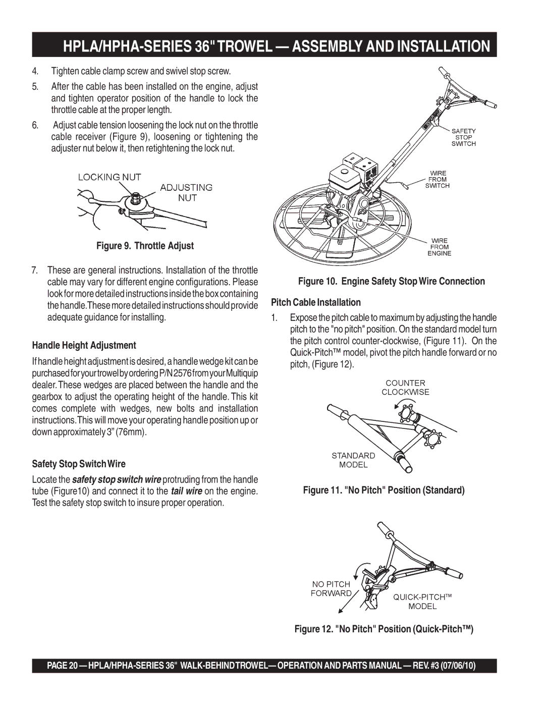
Tighten cable clamp screw and swivel stop screw
Handle Height Adjustment
Safety Stop SwitchWire
Against the yoke boss
Insert the cable end through the yoke eyelet Figure
Slack from the cable
HPLA/HPHA-SERIES 36TROWEL- PRE-INSPECTION
Instructions
Before Starting
Engine Oil Check
HPLA/HPHA-SERIES 36TROWEL- PRE-INSPECTION
Controls
HPLA/HPHA-SERIES 36TROWEL Initial START-UP
Lifting the Trowel Onto the Slab
Auxiliary Lifting Tube
Lifting Bail Option
Test the Safety Stop Switch
HPLA/HPHA-SERIES 36TROWEL Initial START-UP
ONposition
Place the Choke Lever in the Closed position
HPLA/HPHA-SERIES 36TROWEL Operation
Pitchingthe Blaces
Quick Pitch Handle
Maneuvering the Trowel
HPLA/HPHA-SERIES 36TROWEL Operation
While operating this equipment
These blades have been specifically designed for
Clip-On Float Blades Optional
Combo Blades
Grinding Attachments
Trowel Arm Adjustment Tool
HPLA/HPHA-SERIES 36TROWEL Options
Reference manufacturer engine Instructions
HPLA/HPHA-SERIES 36TROWEL Maintenance Engine
Engine Maintenance
HPLA/HPHA-SERIES 36TROWEL Maintenance Engine
Engineaircleaner
Daily
Weekly
HPLA/HPHA-SERIES 36TROWEL Maintenance
Maintenance Schedule
HPLA/HPHA-SERIES 36TROWEL Maintenance
Spider Removal
Trowel Arm Removal
Remove the trowel arm from the spider plate
Trowel Blade Removal
Trowel Arm Flatness Test
Re-Assembly
Testing
Before removing the blades
Changing a Blade
HPLA/HPHA-SERIES 36TROWEL Maintenance
V-Belt will tension itself
Changing The V- Belt
Work belt around and off the bottom pulley and remove belt
HPLA/HPHA-SERIES 36TROWEL Troubleshooting Trowel
Trowel Troubleshooting
HPLA/HPHA-SERIES 36TROWEL Troubleshooting Trowel
Engine Troubleshooting
HPLA/HPHA-SERIES 36TROWEL Troubleshooting Engine
Difficult to start
HPLA/HPHA-SERIES 36TROWEL Explanation of Codes
Xxxxx only Not Used on
HPLA/HPHA-SERIES 36TROWEL Suggested Spare Parts
HPLA/HPHA-SERIES 36TROWEL Nameplate and Decals
Nameplates and Decals
Decal PRE-LOAD Indicator
Service Dept
Decal Power Trowel
Nameplate and Decals
HPLA/HPHA-SERIES 36TROWEL Standard Handle Assy
Standard Handle Assy Detail a See Detail B
HPLA/HPHA-SERIES 36TROWEL Standard Handle Assy
HPLA/HPHA-SERIES 36TROWEL QUICK-PITCH Handle Assy
HPLA/HPHA-SERIES 36TROWEL QUICK-PITCH Handle Assy
HPLA/HPHA-SERIES 36TROWEL Quick Pitch Handle Assy
Quick Pitch Handle Assy
HPLA/HPHA-SERIES 36TROWEL Quick Pitch Handle Assy
HPLA/HPHA-SERIES 36TROWEL 4-BLADE Spider Assy
Blade Spider Assy
Wear Ring
Flange Bearing
Wear Plate
Bearing Insert
HPLA/HPHA-SERIES 36TROWEL Gearbox & Engine Mounts Assy
Gearbox & Engine Mounts Assy
SEAL, OIL National #470954
FLANGE, Input Shaft
RING, O -139 Buna N
SHIM, Input 0.002 Thick
HPLA/HPHA-SERIES 36TROWEL Gearbox & Engine Mounts Assy
ARM, Yoke
PIN, Yoke
Stationary Guard Ring
BUSHING, Guard Ring
HPLA/HPHA-SERIES 36TROWEL Engine Assy
Engine Assy
HPLA/HPHA-SERIES 36TROWEL Engine Honda Assy
HPLA/HPHA-SERIES 36TROWEL Guard Ring Assy
Guard Ring Assy
20808
1940
Blades & ARM Adjustment Fixture Assy
HPLA/HPHA-SERIES 36TROWEL Blades & ARM ADJ. Fixture Assy
0202 Hhcs 5/16-18X1 Ring 0201
1434
1162A
7281
HPLA/HPHA-SERIES 36TROWEL Lifting Bail ASSY. Option
Lifting Bail ASSY. Option
0205 Hhcs 3/8-16X1 1394 Fhscs 3/8-16X1 0166A
HPLA/HPHA-SERIES 36TROWEL Lifting Bail ASSY. Option
10229 Hhcs 5/16-24X1 0161C
Honda GX240K1QA2 Engine AIR Cleaner Assy
AIR Cleaner Assy
COVER, AIR Cleaner
GROMMET, AIR Cleaner
COLLAR, AIR Cleaner
Collar B, AIR Cleaner
Honda GX240K1QA2 Engine Camshaft Assy
Camshaft Assy
SPRING, Weight Return
ROD Push
ARM Valve Rocker
Lifter Valve
Honda GX240K1QA2 Engine Carburetor Assy
Carburetor Assy
PLATE, Lever Setting
Gasket SET
Valve SET, Float
Float SET
Honda GX240K1QA2 Engine Control Assy
Control Assy
ARM, Governor
ROD, Governor
SPRING, Governor
SPRING, Throttle Return
Honda GX240K1QA2 Engine Crankcase Cover Assy
Crankcase Cover Assy
WEIGHT, Governor
HOLDER, Governor Weight
PIN, Governor Weight
GASKET, Case Cover
Honda GX240K1QA2 Engine Crankshaft Assy
Crankshaft Assy
WEIGHT, Balancer
13320ZE2601
13351ZE2010
90745ZE2600 KEY 6.3 X 6.3 X 961006206000
Honda GX240K1QA2 Engine Cylinder Barrel Assy
Cylinder Barrel Assy
SHAFT, Governor ARM
BOLT, Drain Plug
OIL Seal
WASHER, Drain Plug 12MM
Honda GX240K1QA2 Engine Cylinder Head Assy
Cylinder Head Assy
GUIDE, VALVE, OS, Optional
GUIDE, EX. VALVE, OS, Optional
CLIP, Valve Guide
GASKET, Cylinder Head
Honda GX240K1QA2ENGINE FAN Cover Assy
FAN Cover Assy
Switch ASSY., Engine Stop
CLIP, Wire Harness
CLIP, Tube
Shroud
Honda GX240K1QA2 Engine Flywheel Assy
Flywheel Assy
FAN, Cooling
Flywheel Comp
NUT, Special 16MM
KEY, Special Woodruff
Honda GX240K1QA2ENGINE Fueltank Assy
Fuel Tank Assy
Rubber Supporter 107MM
JOINT, Fuel Tank
Tank COMP., Fuel *NH1*, Black
GASKET, Fuel Filler CAP
Honda GX240K1QA2 Engine Ignition Coil Assy
Ignition Coil Assy
GROMMET, Wire
WIRE, Stop Switch 370MM
Coil ASSY., Ignition
CAP ASSY., Noise Suppressor
Honda GX240K1QA2 Engine Muffler Assy
Muffler Assy
Muffler Comp
Protector COMP., Muffler
PROTECTOR, EX. Pipe
PIPE, EX
Honda GX240K1QA2 Engine Piston Assy
Piston Assy
BOLT, Connecting ROD
Ring SET, PISTON, STD
Ring SET, PISTON, 0.75, Optional
PISTON, Standard
Honda GX240K1QA2 Engine Recoil Starter Assy
Recoil Starter Assy
Honda GX240K1QA2 Engine Recoil Starter Assy
Honda GX240K1QA2 Engine Engine Labels
Engine Labels
EMBLEM, Internal
LABEL, Caution
MARK, CHOKE, External
MARK, OIL ALERT, E
Special Expediting Service
Payment Terms
Freight Policy
Minimum Order
Page
HERE’S HOW to GET Help