GENERATOR OUTPUTS

GENERATOR OUTPUT VOLTAGES

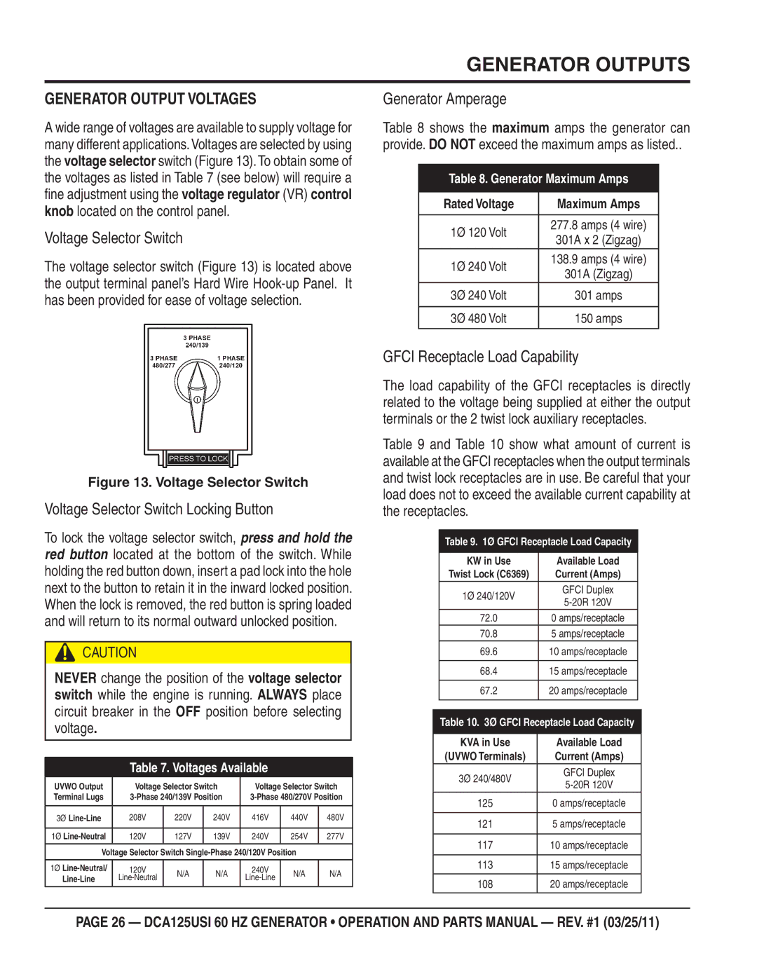
A wide range of voltages are available to supply voltage for many different applications.Voltages are selected by using the voltage selector switch (Figure 13). To obtain some of the voltages as listed in Table 7 (see below) will require a

ne adjustment using the voltage regulator (VR) control knob located on the control panel.

Voltage Selector Switch

The voltage selector switch (Figure 13) is located above the output terminal panel’s Hard Wire Hook-up Panel. It has been provided for ease of voltage selection.

Generator Amperage

Table 8 shows the maximum amps the generator can provide. DO NOT exceed the maximum amps as listed..

Table 8. Generator Maximum Amps

Rated Voltage

Maximum Amps


1Ø 120 Volt

277.8 amps (4 wire)

301A x 2 (Zigzag)


1Ø 240 Volt

138.9 amps (4 wire)

301A (Zigzag)


3Ø 240 Volt

301 amps


3Ø 480 Volt

150 amps


Figure 13. Voltage Selector Switch

Voltage Selector Switch Locking Button

To lock the voltage selector switch, press and hold the red button located at the bottom of the switch. While holding the red button down, insert a pad lock into the hole next to the button to retain it in the inward locked position. When the lock is removed, the red button is spring loaded and will return to its normal outward unlocked position.

CAUTION

NEVER change the position of the voltage selector switch while the engine is running. ALWAYS place circuit breaker in the OFF position before selecting voltage.

Table 7. Voltages Available

UVWO Output

Voltage Selector Switch

Voltage Selector Switch

Terminal Lugs

3-Phase 240/139V Position

3-Phase 480/270V Position


Line-Line

208V

220V

240V

416V

440V

480V


Line-Neutral

120V

127V

139V

240V

254V

277V


Voltage Selector Switch Single-Phase 240/120V Position


Line-Neutral/

120V

N/A

N/A

240V

N/A

N/A

Line-Line

Line-Neutral

Line-Line


GFCI Receptacle Load Capability

The load capability of the GFCI receptacles is directly related to the voltage being supplied at either the output terminals or the 2 twist lock auxiliary receptacles.

Table 9 and Table 10 show what amount of current is available at the GFCI receptacles when the output terminals and twist lock receptacles are in use. Be careful that your load does not to exceed the available current capability at the receptacles.

Table 9. 1Ø GFCI Receptacle Load Capacity

KW in Use

Available Load

Twist Lock (C6369)

Current (Amps)

1Ø 240/120V

GFCI Duplex

5-20R 120V


72.0

0 amps/receptacle

70.8

5 amps/receptacle

69.6

10 amps/receptacle


68.4

15 amps/receptacle


67.2

20 amps/receptacle


Table 10. 3Ø GFCI Receptacle Load Capacity

KVA in Use

Available Load

(UVWO Terminals)

Current (Amps)

3Ø 240/480V

GFCI Duplex

5-20R 120V


125

0 amps/receptacle


121

5 amps/receptacle


117

10 amps/receptacle


113

15 amps/receptacle


108

20 amps/receptacle


PAGE 26 — DCA125USI 60 HZ GENERATOR • OPERATION AND PARTS MANUAL — REV. #1 (03/25/11)

Page 26
Image 26
Multiquip DCA125USI manual Generator Outputs, Generator Output Voltages

DCA125USI specifications

The Multiquip DCA125USI is a high-performance portable diesel generator renowned for its reliability, efficiency, and robust construction, making it an ideal choice for construction sites, events, and remote locations requiring continuous power. Engineered for durability, this generator features a solid and compact design that allows seamless transport while providing ample power to meet demanding applications.

One of the standout features of the DCA125USI is its powerful 125 kVA output, capable of supplying electricity to a wide range of equipment simultaneously. With a fuel-efficient Tier 4 compliant engine, this generator not only delivers high performance but also addresses environmental concerns through reduced emissions. Operating at low noise levels, the DCA125USI ensures a quieter work environment, making it suitable for urban areas and noise-sensitive locations.

In terms of technology, the DCA125USI is equipped with a state-of-the-art digital control panel that offers advanced monitoring capabilities, allowing users to easily track the generator's performance, fuel consumption, and overall health. This user-friendly interface simplifies operation and enhances the overall experience for users, whether they are seasoned professionals or first-time operators. Additionally, the generator is fitted with automatic voltage regulation (AVR), which provides stable power output, protecting connected equipment from voltage fluctuations.

Safety is a priority with the Multiquip DCA125USI, as evidenced by its comprehensive set of protection features, including low oil pressure shutdown, high-temperature shutdown, and overload protection. These safety mechanisms ensure the longevity of the engine and the generator's components while safeguarding connected equipment against potential damage.

Another notable characteristic is its large fuel tank, which allows for extended run times, reducing the need for frequent refueling. This feature is particularly beneficial in situations where access to fuel is limited or where continuous operation is critical.

In conclusion, the Multiquip DCA125USI is a versatile and dependable portable diesel generator, catering to a wide variety of applications. Its combination of high output, advanced technology, and robust safety features make it an excellent investment for contractors, event organizers, and anyone in need of reliable power in challenging environments. With this generator, users can have peace of mind knowing they have a powerful energy solution at their disposal.