Model dca20spxu2
Proposition 65 warning
Administrator
Reporting Safety Defects
DCA20SPXU2 60Hz Generator
Table of Contents
Choose from three easy options
SaFetY messages
Safety Information
Generator saFetY
General saFetY
Restricted. If the air fl ow is
Engine saFetY
If operating in speed ranges above the maximum allowable
From fuel vapors or if fuel is spilled on a hot engine
Fuel saFetY
ToWing saFetY
„ never use fuel as a cleaning agent
BatterY saFetY
EleCtriCal saFetY
Power Cord/Cable safety
Grounding safety
Label must remain with the engine for its entire life
Environmental saFetY/deCommissioning
Emissions inFormation
Emission Control label
Generator Specifications
Specifications
Dimensions
Dimensions
Typical Generator Grounding Application
Installation
Generator Grounding
Outdoor Installation
Indoor Installation
Mounting
General Information
Item no
Generator Major Components
Trailer Components
Trailer Major Components
OFF
Generator conTROL Panel
OFF
Engine Control Panel
Engine control Panel
Terminal legs O and Ground are considered bonded grounds
Output Terminal Familiarization
Output Terminal Panel is provided with the following
VAC Gfci Receptacles
Removing the Plastic Face Plate Hard Wire Hookup Panel
Over Current Relay
Connecting Loads
Load Application/Generator output
Single Phase Load
Generator Amperage
1Ø-240 Output Terminal Voltage
UOV Terminal Output Voltages
1Ø-120 Output Terminal Voltage
Fuel Check
Inspection/SETUP
Circuit Breakers
Lubrication Oil
Coolant Antifreeze/Summer Coolant/ Water
Refueling Procedure
Remove fuel cap from filler neck and fill fuel tank Figure
Operation in Freezing Weather
Cleaning the Radiator
Air Cleaner Fan Belt Tension
Battery
Alternator
Battery Cable Installation
Wiring
When connecting battery do the following
Engine’s exhaust contains harmful emissions
Generator START-UP Procedure manual
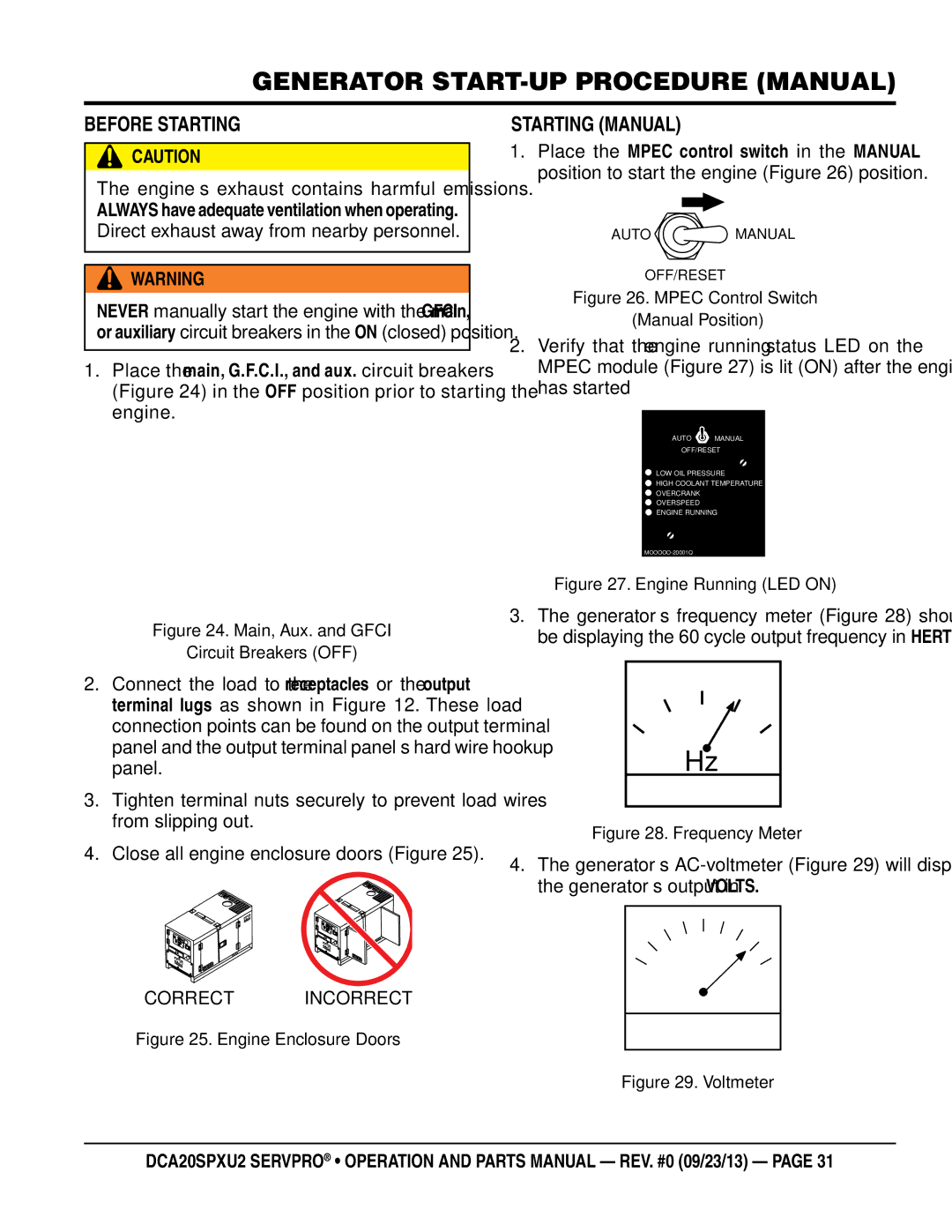
Before Starting
Starting Manual
Voltage Adjust Control Knob
Place the Mpec Control Switch in the Auto position
Starting Auto Mode
Before connecting this generator to any
Without this transfer switch
Emergency Shutdown Procedure
Normal Shutdown Procedure
General Inspection Air Cleaner
Maintenance
Air Cleaner with Dust Indicator
Fuel Tank Inspection
Cleaning Inside the Fuel Tank
Fuel Addition
Removing Water from the Fuel Tank
Flushing Out Radiator and Replacing Coolant
Radiator Cleaning
Check Oil Level
Replacing Oil Filter
Jacket Water Heater/Battery Charger
Wheel Bearings
Trailer Maintenance
Adjustable Channel
Wheel Hub Adjustment
Leaf Suspension Components
Leaf Suspension
Common Causes For loss oF trailer
Trailer guidelines
Coupling to tHe toW veHiCle
Driving Conditions
Trailer toWing tips
InoperaBle Brakes, ligHts or mirrors
Trailer vin tag
Side vieW mirrors
EleCtriCal ConneCtor
ToW veHiCle
Suspension sYstem
Ball HitCH Coupler
SaFetY CHains
JaCkstand
Coupler tYpes
Coupling the trailer to the tow vehicle Ball Coupler
Lock washer and hitch frame
Connecting trailer lights
Attaching safety Chain
Uncoupling the Ball Hitch
Pintle Coupler and pintle Hook
Pintle HitCH Coupler
Coupling trailer to tow vehicle pintle Coupler
Tire saFetY Unsafe tires, lug nuts or Wheels
Be sure lug nuts are tight before each tow
Determining load limit of trailer
Step
Tighten lug nuts before each tow
Tire Fundamentals
Determining load limit of tow vehicle step
P indicates the tire is for passenger vehicles
Table a. speed rating
Uniform tire Quality grading standards utQgs
Tire repair
Tire safety tips
Replacing Worn or damaged tires
Lug nut torque requirements
Lights and signals
Wheel rims
Wheels, Bearings and lug nuts
Figure L. Trailer to Tow Vehicle Wiring Diagram
Color Code
Generator Wiring Diagram
Engine Wiring Diagram
Jacket Water Heater Wiring Diagram
AC Voltmeter defective?
Troubleshooting Generator
Troubleshooting engine
Troubleshooting engine
Dipstick
Explanation of Code in Remarks Column
Repair kit, Fuel Pump
Suggested Spare Parts
Generator Assy
8001070003
B1110001402
7961025004
0601822643
Control box Assy
0601870433
M1213001402
0330000480
0330000250
Control box Assy
0601801040
M1223001003
0601807641
0601806844
Engine and Radiator Assy
M1303200304
M1923200104
8972606490
8943142633
Engine and Radiator Assy
0605511395
0602022561
0603306590
0603300285
Output Terminal Assy
0039308000
M1230700203
M9220000204
M9220000104
Battery Assy
0602220920
0602220185
B9310500014
M9103000304
Muffler Assy
Replaces
M1330100803
M1333002803
8970420280
Fuel Tank ASSY. Internal
M1363200004
M1363000212
Y0605505073
EE57348
Fuel Tank ASSY. Trailer mOUNTED
84454
EE35976
6109204
5284
Trailer Assy
9514
0205 SCREW, HHC 3/8 16 x 4001
9502
9503 NUT, Nyloc 5/8 9505 FENDER, 8 x 30 x
Battery Charger Assy
EE56557
LC125002
34530
EE6009
Jacket Water Heater Assy
TPS051GT10000 HEATER, 500W, 120 VAC
Enclosure Assy
M1493104903
M1413003302
M1413400004
M1423002302
Enclosure Assy
34A M1493405704
M1453003803
33A M1493405604
M1453003903
Rubber Seals Assy
REMArks
Nameplate and Decals Assy
M15000190
M1550001803
M15000180
M1550001904
Nameplate and Decals Assy
38A$ EE57078
36$ EE57072
36A$ EE57073
38$ EE57077
FreigHt poliCY
Terms and Conditions of Sale Parts
Servpro RMA Department is here to serve you
Servpro Warranty/RMA
Industrial Blvd Gallatin, TN Phone