FS 1 CONCRETE SAW — INSPECTION -BLADE PLACEMENT

WARNING

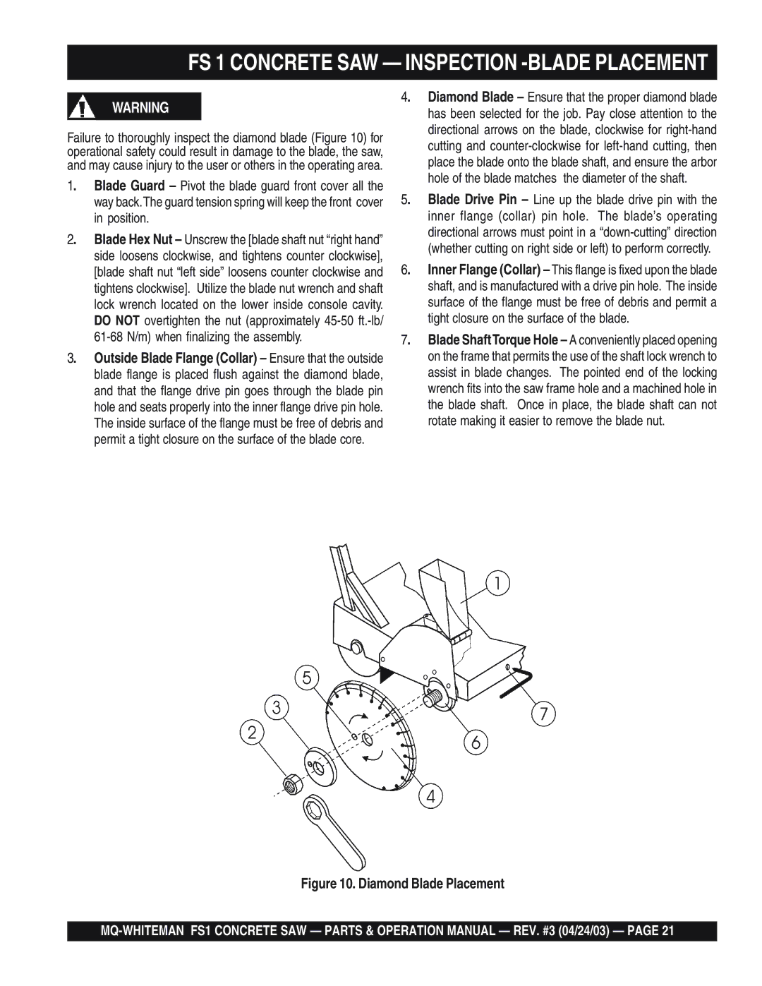
Failure to thoroughly inspect the diamond blade (Figure 10) for operational safety could result in damage to the blade, the saw, and may cause injury to the user or others in the operating area.

1.

Blade Guard – Pivot the blade guard front cover all the


way back.The guard tension spring will keep the front cover


in position.

2.

Blade Hex Nut – Unscrew the [blade shaft nut “right hand”


side loosens clockwise, and tightens counter clockwise],


[blade shaft nut “left side” loosens counter clockwise and


tightens clockwise]. Utilize the blade nut wrench and shaft


lock wrench located on the lower inside console cavity.


DO NOT overtighten the nut (approximately 45-50 ft.-lb/


61-68 N/m) when finalizing the assembly.

3.

Outside Blade Flange (Collar) – Ensure that the outside


blade flange is placed flush against the diamond blade,

and that the flange drive pin goes through the blade pin hole and seats properly into the inner flange drive pin hole. The inside surface of the flange must be free of debris and permit a tight closure on the surface of the blade core.

4. Diamond Blade – Ensure that the proper diamond blade has been selected for the job. Pay close attention to the directional arrows on the blade, clockwise for right-hand cutting and counter-clockwise for left-hand cutting, then place the blade onto the blade shaft, and ensure the arbor hole of the blade matches the diameter of the shaft.

5. Blade Drive Pin – Line up the blade drive pin with the inner flange (collar) pin hole. The blade’s operating directional arrows must point in a “down-cutting” direction


(whether cutting on right side or left) to perform correctly.

6.

Inner Flange (Collar) – This flange is fixed upon the blade


shaft, and is manufactured with a drive pin hole. The inside


surface of the flange must be free of debris and permit a


tight closure on the surface of the blade.

7.

Blade ShaftTorque Hole – A conveniently placed opening


on the frame that permits the use of the shaft lock wrench to


assist in blade changes. The pointed end of the locking


wrench fits into the saw frame hole and a machined hole in

the blade shaft. Once in place, the blade shaft can not rotate making it easier to remove the blade nut.

Figure 10. Diamond Blade Placement

MQ-WHITEMAN FS1 CONCRETE SAW — PARTS & OPERATION MANUAL — REV. #3 (04/24/03) — PAGE 21

Page 21
Image 21
Multiquip FS 1 Concrete SAW Inspection -BLADE Placement, Position, 61-68 N/m when finalizing the assembly

FS 1 specifications

The Multiquip FS 1 is a versatile piece of equipment designed for efficient fuel management and transfer. Catering primarily to construction sites, agriculture, and industrial applications, the FS 1 is known for its compact design, robust performance, and reliable functionality.

One of the main features of the Multiquip FS 1 is its high-capacity fuel tank, which is engineered to hold a substantial volume of diesel or gasoline, allowing users to refuel equipment without frequent interruptions. This fuel tank is equipped with a durable, weather-resistant cover that ensures protection against various environmental factors, extending the life of the equipment.

In terms of technology, the FS 1 incorporates advanced pumping systems that facilitate rapid fuel transfer. The pump is designed for low noise operation, reducing disturbances on job sites while ensuring efficient fuel flow. Furthermore, the inclusion of an automatic shutoff feature ensures safety during fueling operations by preventing overflows and spills, thus minimizing environmental risks.

The FS 1 is characterized by its mobility. Equipped with sturdy wheels and a reliable tow hitch, it can be easily transported from one location to another, simplifying the logistics of fuel distribution on-site. This portability is particularly beneficial in large construction projects where multiple machines require fueling at varied intervals.

Ergonomically designed, the FS 1 features user-friendly controls that simplify operation. Operators can easily manage fuel transfers, check gauge readings, and monitor flow rates without extensive training. Additionally, the FS 1 is designed to be compatible with various fuel nozzles, making it a versatile choice for different fueling needs.

The construction of the FS 1 emphasizes durability and longevity. Built with high-quality materials, it is resistant to corrosion and wear, making it suitable for demanding environments. The design also prioritizes ease of maintenance, with accessible components that allow for quick inspections and repairs.

In summary, the Multiquip FS 1 stands out for its combination of efficiency, safety, and mobility. It is an essential tool for professionals who require a reliable fuel management solution that is easy to operate and maintain. With its innovative design and advanced features, the FS 1 simplifies the fueling process, allowing users to focus on their core tasks and enhancing overall productivity on the job site.