GLW-180H —WELDER OPERATING INSTRUCTIONS
Welding Cables
The required cable welding size is governed by this simple rule:The longer the welding cable, or the greater the welding current, the thicker (copper strands) the calbe must be.
Select a welding cable with adequate thickness according to the cable length and welding amperage (current) as listed in Table 5.
Table 5. Welder Cable Sizes
Welder Output | Cable Length | Cable Size | |
Current | |||
|
| ||
|
|
| |
| 50 | No. 3 | |
|
|
| |
| 100 | No. 3 | |
|
|
| |
| 125 | No. 3 | |
100 |
|
| |
150 | No. 3 | ||
|
|
| |
| 200 | No. 3 | |
|
|
| |
| 250 | No. 3 | |
|
|
| |
| 300 | No. 3 | |
|
|
| |
| 50 | No. 3 | |
|
|
| |
| 100 | No. 3 | |
|
|
| |
| 125 | No. 3 | |
150 |
|
| |
150 | No. 3 | ||
|
|
| |
| 200 | No. 2 | |
|
|
| |
| 250 | No. 1 | |
|
|
| |
| 300 | No. 1 | |
|
|
| |
| 50 | No. 3 | |
|
|
| |
| 100 | No. 3 | |
|
|
| |
| 125 | No. 3 | |
|
|
| |
200 | 150 | No. 2 | |
|
|
| |
| 200 | No. 1 | |
|
|
| |
| 250 | No. 1/0 | |
|
|
| |
| 300 | No. 1/0 | |
|
|
|
Duty Cycle
The duty cycle for the generator/welder is based on 10 minute intervals. See Table 6 below.
Table 6. Duty Cycle
Welding | 110 or | 125 | 145 | 160 | 180 | |
Current | Less | |||||
|
|
|
| |||
|
|
|
|
|
| |
Duty | 100 | 80 | 60 | 50 | 40 | |
Cycle% | ||||||
|
|
|
|
| ||
|
|
|
|
|
|
CAUTION:
NEVER switch the current range selector switch during any welding operation.
1.Connect the welding cables (electrodes) to the generator's output terminals (Figure 4). For minimum welding current
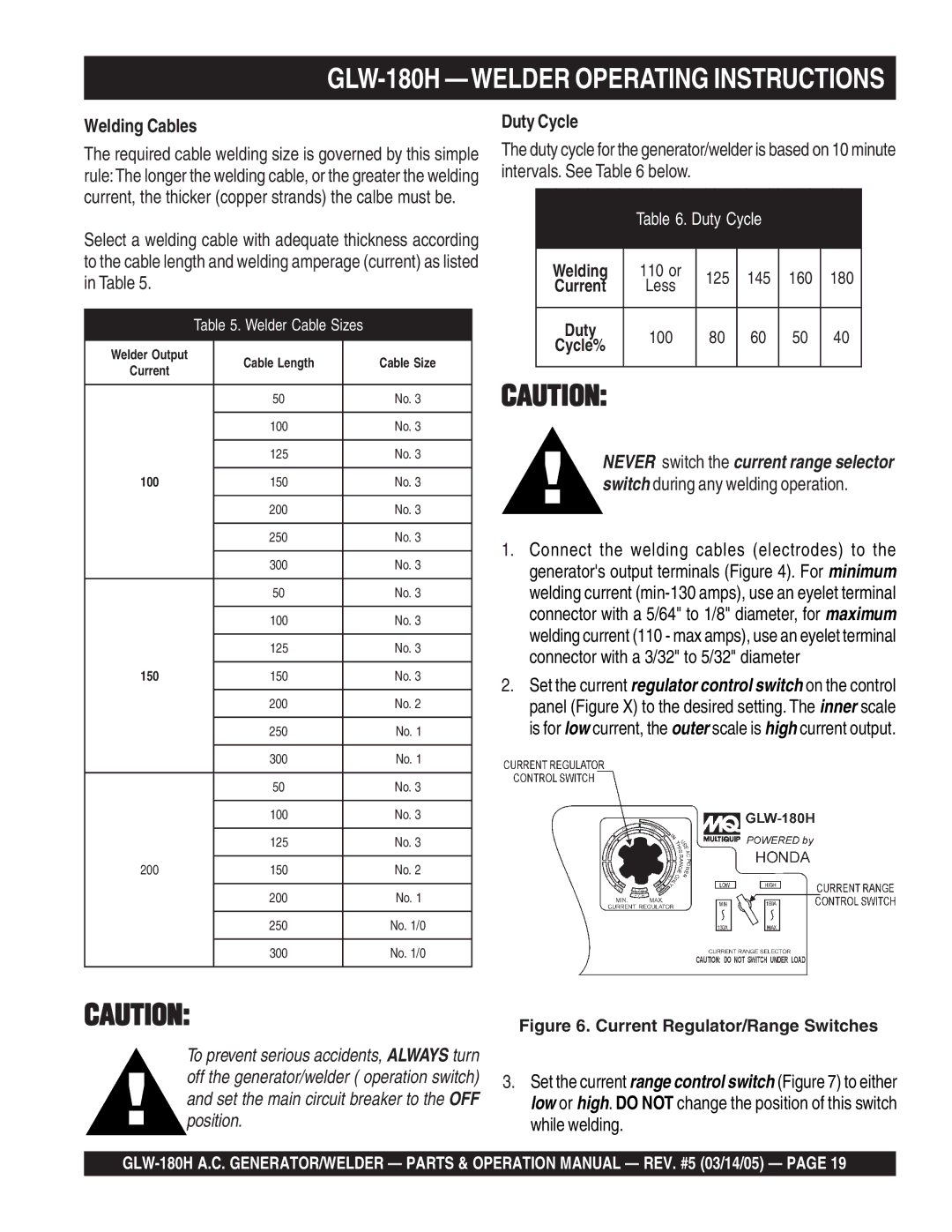
2.Set the current regulator control switch on the control panel (Figure X) to the desired setting. The inner scale is for low current, the outer scale is high current output.
CAUTION: | Figure 6. Current Regulator/Range Switches |
To prevent serious accidents, ALWAYS turn off the generator/welder ( operation switch) and set the main circuit breaker to the OFF position.
3.Set the current range control switch (Figure 7) to either low or high. DO NOT change the position of this switch while welding.