CAUTION :
When using a combination of dual receptacles, total load should not exceed the rated capacity of the generating.
The definitions below describe the controls and functions of the of the
1.Ground Terminal Equipment – If required ground equipment (power tools etc,) to this ground terminal.This ground is not EARTH ground.
2.120 VAC Twist Lock Receptacle – This unit is supplied with one Twist Lock NEMA
3.120 VAC GFCI Receptacle – This unit is supplied with one Duplex NEMA (GFCI)
4.ACVoltmeter – This voltmeter indicates (with a mark) the rated 60 Hz, 120 VAC single phase output voltage. In addition the voltmeter can also be used as a diagnostic tool.
If the voltmeter indicator (needle) is below the rated voltage, engine problems may exist (low/high RPM's).To prevent damage to the generator or power tools turn the generator OFF and consult your authorized Multiquip service dealer.
5.Circuit Breaker – This
6.Operation Switch – Must be in the up position (ON) for normal operation.To
GLW-180H — INSTRUMENTATION
7.Current Regulator – Use this dial to adjust the welder's output to the desired setting.
8.Idle Control Switch – This unit is provided with an automatic idle control for noise suppression and reduced fuel consumption.The automatic idle control automatically enGLWges under a
With the automatic idle control switched “ON”, the engine revolutions will automatically drop to about 2500 rpm (low- speed operation) within 3 seconds after the load stops.
When the operation is resumed, the engine speed is automatically increased to about 3600 rpm
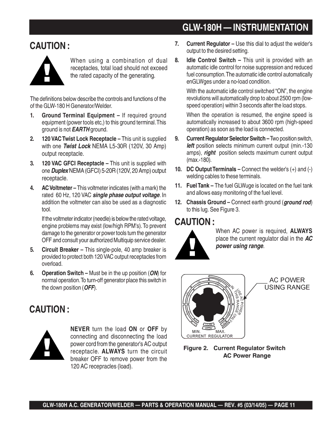
9.Current Regulator Selector Switch
10.DC OutputTerminals – Connect the welder's (+) and
11.Fuel Tank – The fuel GLWuge is located on the fuel tank and allows easy monitoring of the fuel level.
12.Chassis Ground – Connect earth ground (ground rod) to this lug. See Figure 3.
CAUTION :
When AC power is required, ALWAYS place the current regulator dial in the AC power using range.
CAUTION :
NEVER turn the load ON or OFF by |
| |
connecting and disconnecting the load |
| |
power cord from the generator's AC output | Figure 2. Current Regulator Switch | |
receptacle. ALWAYS turn the circuit | ||
AC Power Range | ||
breaker OFF to remove power from the | ||
| ||
120 AC recepracles (load). |
|