maintenance

checking trowel arm straightness

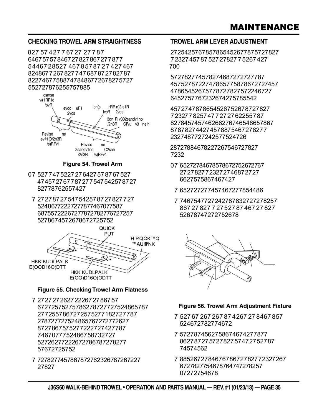
Trowel arms (Figure 54) can be damaged by rough handling, such as dropping the trowel on the pad, or by striking exposed plumbing, forms, or rebar while in operation. A bent trowel arm will not allow the trowel to operate in a smooth fluid rotation. If bent trowel arms are suspect, check for flatness as follows:

LEVER


MOUNTING


SLOT

ROLL PIN

BLADE ATTACHMENT


BOLT HOLE


HOLE


FLAT OF HEXAGONAL


SHAFT (TOP OF ARM)

TROWEL ARM

ROUND SHAFT

SECTION TROWEL ARM

HEXAGONAL (HEX)

SHAFT SECTION

Figure 54. Trowel Arm

1.Use a thick steel plate, granite slab or any surface which is true and flat, to check all six sides of each trowel arm for flatness (Figure 55).

2.Check each of the six sides of the trowel arm (hex section). A feeler gauge of .004 inch (0.10 mm) should not pass between the flat of the trowel arm and the test surface along its length on the test surface.

TROWEL

ARM

FLAT TEST

SURFACE

FEELER GAUGE

trowel arm Lever adjustment

The easiest and most consistent way to adjust the trowel arm lever is to use the Trowel Arm Adjustment Fixture (P.N. 1817).

As each trowel arm is locked into the fixture, the arm bolt is adjusted to where it contacts a stop on the fixture. This will consistently adjust all of the trowel arms, keeping the finisher as flat and evenly pitched as possible.

This fixture will allow consistent adjustment of the trowel arm lever. It comes with all the hardware necessary to properly accomplish this maintenance and instructions on how to properly utilize this tool. Adjusting the trowel arm lever without a fixture requires a special talent.

Perform the following procedure when adjusting the trowel arm lever:

1.Unscrew the locking bolts on the adjustment fixture and place the trowel arm (lever attached) into the fixture channel as shown in Figure 56.

2.Ensure the fixture arm is in the up position.

3.A thin shim may be required to cover the blade holes on the trowel arm. Make sure to align the trowel adjustment bolt with the fixture adjustment bolt.

TROWEL

ARM

ARM LEVER FIXTURE

ARM

ADJUSTMENT

BOLT

SHIM

DISTANCE

(.005 IN/0.127 MM)

FEELER GAUGE

(.004 IN/0.10 MM)

Figure 55. Checking Trowel Arm Flatness

3. Next, check the clearance between the round shaft

ADJUSTMENT

BOLT

LOCKING

BOLTS

TROWEL ARM

ADJUSTMENT FIXTURE

.010 INCH

and the test surface as one of the flat hex sections of

the arm rests on the test surface. Rotate the arm to

each of the flat hex sections and check the clearance

of the round shaft. Use a feeler gauge (Figure 56) of

.005 inch (0.127 mm). Each section should have the

same clearance between the round of the trowel arm

shaft and the test surface.

4. If the trowel arm is found to be uneven or bent, replace

the trowel arm.

Figure 56. Trowel Arm Adjustment Fixture

4.Use an allen wrench to tighten the locking bolts securing the trowel arm in place.

5.Adjust the bolt distance shown in Figure 56 to match one of the arms. The other arms will be adjusted to match this distance.

6.Loosen the locking nut on the trowel arm lever, then turn the trowel arm adjusting bolt until it barely touches (.010") the fixture adjusting bolt.

j36s60 WALK-BEHIND TROWEL • operatION And parts manual — rev. #1 (01/23/13) — page 35

Page 35
Image 35
Multiquip J36S60 manual Checking trowel arm straightness, Trowel arm Lever adjustment, Shaft and the test surface

J36S60 specifications

The Multiquip J36S60 is a versatile and robust generator designed for various applications, ranging from construction sites to outdoor events. With a focus on reliable power and durability, the J36S60 is engineered to meet the demanding requirements of professionals and contractors alike.

At the heart of the J36S60 is its powerful engine, which provides a maximum output of 36 kVA. This generator is equipped with a 60Hz, 240V output, making it suitable for a wide range of equipment and tools. The J36S60 features a fuel-efficient design, allowing for extended run times that minimize downtime on job sites. It can operate for hours on end, ensuring that you have continuous power for critical tasks.

One of the standout features of the J36S60 is its state-of-the-art control panel. The intuitive control panel provides clear access to various functions, making it easy for users to monitor power output, fuel levels, and maintenance intervals. The panel includes circuit breakers, hour meters, and an easy-to-read digital display, ensuring that operators have all necessary information at their fingertips.

Additionally, the Multiquip J36S60 generator incorporates advanced technologies for noise reduction and fuel efficiency. Its innovative design includes sound-dampening materials and a high-capacity silencer, resulting in quieter operation compared to traditional generators. This feature makes it especially suitable for urban environments where noise regulations are strictly enforced.

The J36S60 is built with durability in mind. The heavy-duty steel frame and powder-coated finish ensure that it can withstand the rigors of demanding job sites and adverse weather conditions. Furthermore, the unit is designed for easy transport, with integrated lifting hooks and a compact design that allows for convenient positioning and relocation.

Safety is a priority with the J36S60, which comes equipped with multiple safety features including low oil shutdown, overload protection, and an emergency stop button. These safety mechanisms ensure that both the operator and the machinery are protected during operation.

Overall, the Multiquip J36S60 is a high-performance generator that excels in providing reliable power in a variety of settings. Its combination of power output, efficient fuel consumption, user-friendly controls, and robust build quality makes it an excellent choice for construction professionals, event coordinators, and anyone in need of dependable portable power.