DCA-70SSIU (60 Hz) — GENERATOR START-UP PROCEDURE (MANUAL)
10.Verify that the Engine Running status LED on the MPEC unit (Figure 45) is ON (lit) after the engine has been started.
Figure 45. Engine
Running LED (ON)
11.The generator's frequency meter (Figure 46) should be displaying the 60 cycle output frequency in HERTZ.
Figure 46. Frequency Meter (Hz)
12.The generator's
Figure 47. Voltmeter
Figure 48.Voltage Adjust Control Knob
13.The ammeter (Figure 49) will indicate zero amps with no load applied.When a load is applied, the ammeter will indicate the amount of current that the load is drawing from the generator.
Figure 49. Ammeter
(No Load)
14.The engine oil pressure gauge (Figure 50) will indicate the oil pressure (kg/ cm2) of the engine. Under normal operating conditions the oil pressure is approximately 35~65 PSI.
15.The coolant temperature gauge (Figure 51) will indicate the coolant temperature. Under normal operating conditions the coolant temperature should be between 165 and 215 degrees Fahrenheit (Green Zone).
Figure 51. Coolant
Temperature Gauge
16.The tachometer gauge (Figure 52) will indicate the speed of the engine when the generator is operating. Under normal operating conditions this speed is approximately 1800 RPM’s.
Figure 52. Engine
Tachometer Gauge
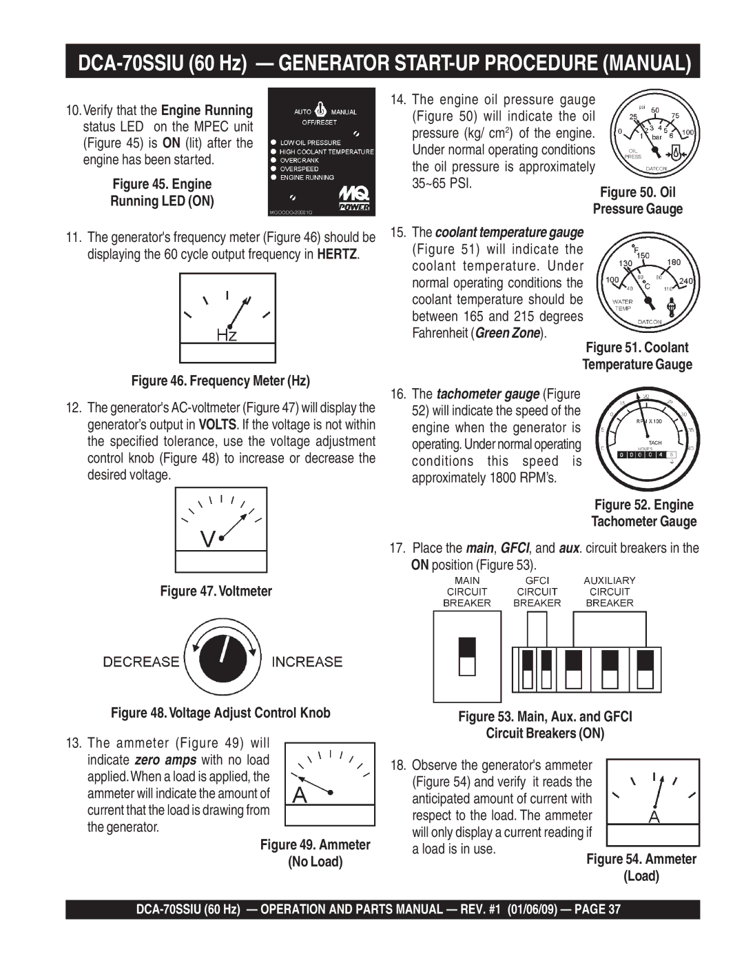
17.Place the main, GFCI, and aux. circuit breakers in the ON position (Figure 53).
Figure 53. Main, Aux. and GFCI
Circuit Breakers (ON)
18.Observe the generator's ammeter (Figure 54) and verify it reads the anticipated amount of current with respect to the load. The ammeter will only display a current reading if a load is in use.