MT-62HS — CONTROLS AND COMPONENTS
13 8
10
1
5
2
12
11
9
3
7
6
4
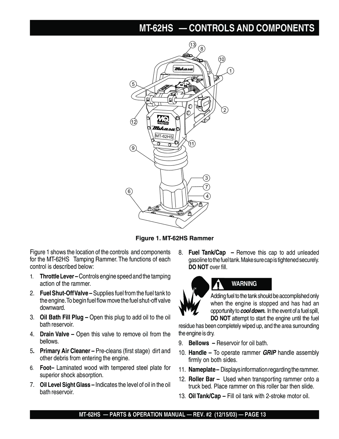
Figure 1. MT-62HS Rammer
Figure 1 shows the location of the controls and components for the MT-62HS Tamping Rammer. The functions of each control is described below:
1.Throttle Lever – Controls engine speed and the tamping action of the rammer.
2.Fuel Shut-OffValve – Supplies fuel from the fuel tank to the engine.To begin fuel flow move the fuel shut-off valve downward.
3.Oil Bath Fill Plug – Open this plug to add oil to the oil bath reservoir.
4.Drain Valve – Open this valve to remove oil from the bellows.
5. Primary Air Cleaner – Pre-cleans (first stage) dirt and other debris from entering the engine.
6.Foot– Laminated wood with tempered steel plate for superior shock absorption.
7.Oil Level Sight Glass – Indicates the level of oil in the oil bath reservoir.
8.Fuel Tank/Cap – Remove this cap to add unleaded gasolinetothefueltank.Makesurecapistightenedsecurely. DO NOT over fill.
WARNING
Adding fuel to the tank should be accomplished only when the engine is stopped and has had an opportunity to cool down. In the event of a fuel spill, DO NOT attempt to start the engine until the fuel
residue has been completely wiped up, and the area surrounding the engine is dry.
9.Bellows – Reservoir for oil bath.
10.Handle – To operate rammer GRIP handle assembly firmly on both sides.
11.Nameplate– Displaysinformationregardingtherammer.
12.Roller Bar – Used when transporting rammer onto a truck bed. Place rammer on this roller bar then slide.
13.Oil Tank/Cap – Fill oil tank with