COMPONENTS
1
10
9
4
3
2
WATER TANK | 5 |
(MVC-80VHW ONLY)
8
7 | 6 |
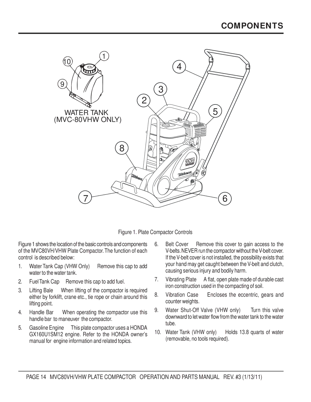
Figure 1. Plate Compactor Controls
Figure 1 shows the location of the basic controls and components of the MVC80VH/VHW Plate Compactor.The function of each control is described below:
1. | Water Tank Cap (VHW Only) – Remove this cap to add |
| water to the water tank. |
2. | FuelTank Cap – Remove this cap to add fuel. |
3.Lifting Bale – When lifting of the compactor is required either by forklift, crane etc., tie rope or chain around this lifting point.
4. Handle Bar – When operating the compactor use this handle bar to maneuver the compactor.
5. Gasoline Engine – This plate compactor uses a HONDA GX160U1SM12 engine. Refer to the HONDA owner's manual for engine information and related topics.
6. Belt Cover – Remove this cover to gain access to the
7. Vibrating Plate – A flat, open plate made of durable cast iron construction used in the compacting of soil.
8. Vibration Case – Encloses the eccentric, gears and counter weights.
9. Water
10. Water Tank (VHW only) – Holds 13.8 quarts of water (removable, no tools required).
PAGE 14 — MVC80VH/VHW PLATE COMPACTOR — OPERATION AND PARTS MANUAL — REV. #3 (1/13/11)