1 Introduction
|
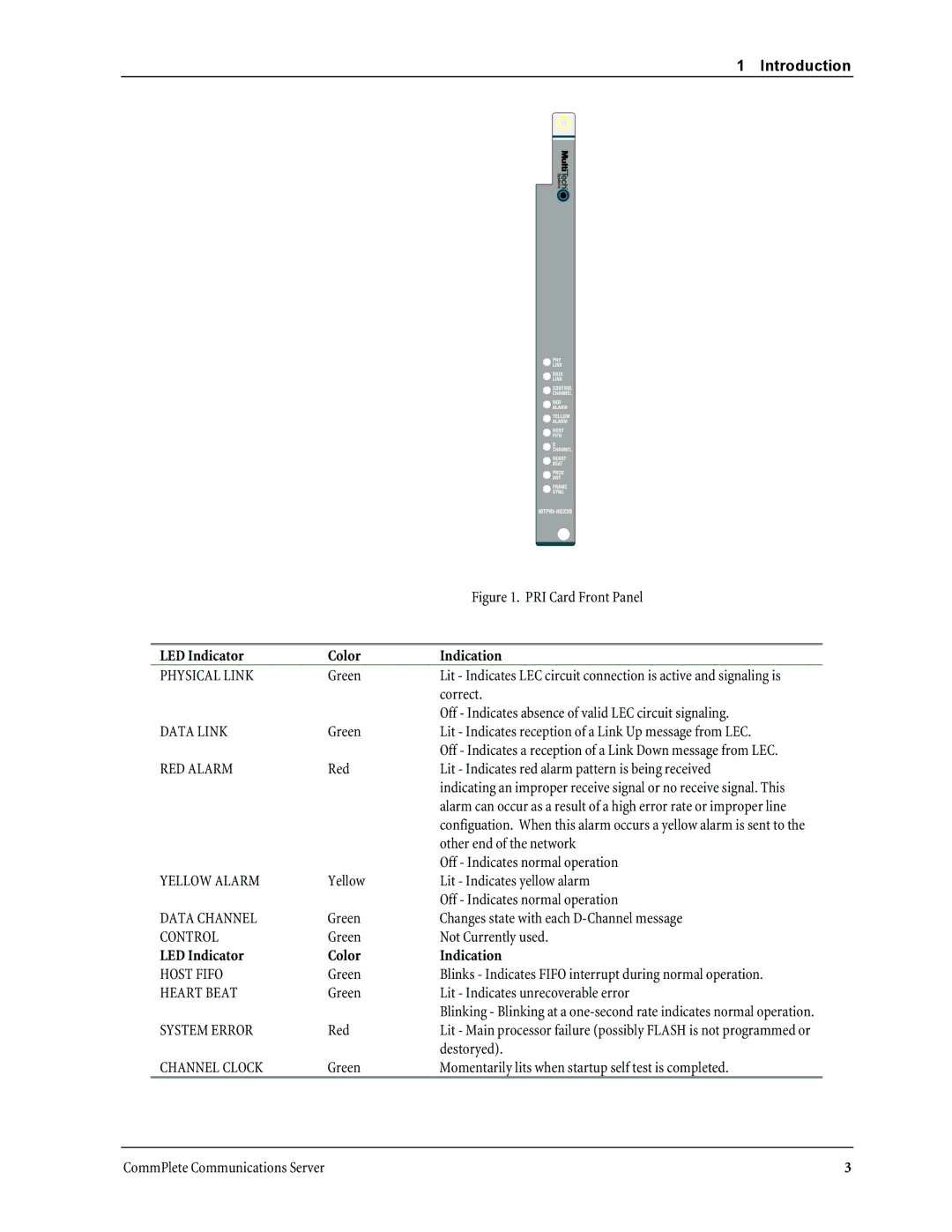
| Figure 1. PRI Card Front Panel |
|
|
|
LED Indicator | Color | Indication |
PHYSICAL LINK | Green | Lit - Indicates LEC circuit connection is active and signaling is |
|
| correct. |
|
| Off - Indicates absence of valid LEC circuit signaling. |
DATA LINK | Green | Lit - Indicates reception of a Link Up message from LEC. |
|
| Off - Indicates a reception of a Link Down message from LEC. |
RED ALARM | Red | Lit - Indicates red alarm pattern is being received |
|
| indicating an improper receive signal or no receive signal. This |
|
| alarm can occur as a result of a high error rate or improper line |
|
| configuation. When this alarm occurs a yellow alarm is sent to the |
|
| other end of the network |
|
| Off - Indicates normal operation |
YELLOW ALARM | Yellow | Lit - Indicates yellow alarm |
|
| Off - Indicates normal operation |
DATA CHANNEL | Green | Changes state with each |
CONTROL | Green | Not Currently used. |
LED Indicator | Color | Indication |
HOST FIFO | Green | Blinks - Indicates FIFO interrupt during normal operation. |
HEART BEAT | Green | Lit - Indicates unrecoverable error |
|
| Blinking - Blinking at a |
SYSTEM ERROR | Red | Lit - Main processor failure (possibly FLASH is not programmed or |
|
| destoryed). |
CHANNEL CLOCK | Green | Momentarily lits when startup self test is completed. |
CommPlete Communications Server | 3 |
